RG5 Processor Clock Example
The RG5 processor is a 16-bit soft core processor, designed more to be small than quick. It's one of my (pdt) current play-time projects.
There are plenty of soft core processors around, e.g. see https://en.wikipedia.org/wiki/Soft_microprocessor and opencores.org. GitHub also has a few, see https://github.com/cliffordwolf/picorv32 for a size optimized RISCV. FPGA vendors also provide PicoBlaze, MicroBlaze, Nios II, Mico8 and Mico32.
I am also working on an assembler/simulator for the RG5 processor. It's written in Tcl. Assembler source files look a lot like assembler, but are Tcl scripts.
For the sake of size:
- the RG5 processor does not have an instruction pipeline
- although from a programming perspective it's 16-bit, it only has an 8-bit ALU
- can address up to 64K data and 128K program space
The RG5 processor doesn't have any general purpose registers. Its only registers are PC (program counter), SR (status register - Z N C V I flags), SP (stack pointer), FP and GP (base pointer registers).
Instead of having general purpose registers, the processor directly uses global or stack-frame variables in FPGA block RAM.
So lets say variable 'a' is on a stack frame:
- 'inc a' will read a's value from memory, increment it, and store it back
- 'add a b' reads a and b values, adds then stores in b
- 'inc *a' will treat a as a pointer, so will dereference before performing the increment operation
- 'add *a *b' will dereference both a and b before adding and storing
The above instructions all assemble to either one, two, or three 16-bit instructions words.
The processor also supports structure operations, which assemble to two or three instruction words:
- 'inc a->x' will dereference and increment the x member of structure a
- 'add a->x b->y' will dereference a and b before adding structure members
But I've yet to fully implement those in my assembler ...
With the above in mind, the clock example assembler code below should be reasonably clear to understand. The clock displays time on 7-segment displays, and has three buttons, mode, up and down, for changing time.
memmap data -start 0x0000 -end 0x01ef
memmap rodata -start 0x01f0 -end 0x01ff
memmap code -start 0x0200 -end 0x03ff

# i/o registers
byte statReg -io 0xffc0
byte ctrlReg -io 0xffc1
byte lsMinutesReg -io 0xffc2
byte msMinutesReg -io 0xffc3
byte lsHoursReg -io 0xffc4
byte msHoursReg -io 0xffc5

# status register bits
constant byte modeBtn 0x01
constant byte upBtn 0x02
constant byte dnBtn 0x04
constant byte timed 0x80

# operating mode
byte mode

# time
byte fractions
byte seconds
byte minutes
byte hours

# for reading buttons
byte btns
byte oldBtns

# scratchpad variable
byte b

# 7-segment display codes
constant byte displayCodes -rodata 0x3f 0x06 0x5b 0x4f 0x66 0x6d 0x7d 0x07 \
        0x7f 0x6f

# ------------------------------------------------------------------------------

section main {
    offsets statReg ctrlReg lsMinutesReg msMinutesReg lsHoursReg msHoursReg \
            mode fractions seconds minutes hours btns oldBtns b %gp 0

    # initialisation
    mv [memmap data -end] %sp
    foreach var {ctrlReg mode fractions seconds minutes hours oldBtns} {
        clr $var
    }

    # wait for timer to trigger
    @ l_waitTimer
    test timed statReg
    bz l_waitTimer

    # check for one button pressed
    mv statReg btns
    foreach val {modeBtn upBtn dnBtn} {
        cmp $val btns
        beq l_btns
    }
    mv btns oldBtns
    cmp 0 mode
    beq l_updateTime
    br l_updateDisplay1

    # update buttons status
    @ l_btns
    mv btns b
    xor oldBtns btns
    and b btns
    mv b oldBtns

    # check for mode button press
    test modeBtn btns
    bz l_mode2
    inc mode
    cmp 3 mode
    bne l_mode1
    clr mode
    @ l_mode1
    mv mode ctrlReg

    # check for display mode
    @ l_mode2
    cmp 0 mode
    beq l_updateTime

    # check for update minutes mode
    cmp 1 mode
    bne l_hours1

    # minutes up
    test upBtn btns
    bz l_mins
    inc minutes
    cmp 60 minutes
    bne l_updateDisplay1
    clr minutes
    br l_updateDisplay1

    # minutes dn
    @ l_mins
    test dnBtn btns
    bz l_updateDisplay1
    dec minutes
    bnn l_updateDisplay1
    mv 59 minutes
    br l_updateDisplay1

    # hours up
    @ l_hours1
    test upBtn btns
    bz l_hours2
    inc hours
    cmp 24 hours
    bne l_updateDisplay1
    clr hours
    br l_updateDisplay1

    # hours dn
    @ l_hours2
    test dnBtn btns
    bz l_updateDisplay1
    dec hours
    bnn l_updateDisplay1
    mv 23 hours
    br l_updateDisplay1

    # update time
    @ l_updateTime
    foreach var {fractions seconds minutes hours} val {20 60 60 24} {
        inc $var
        cmp $val $var
        bne l_updateDisplay1
        clr $var
    }

    # update display
    @ l_updateDisplay1
    callf getDisplayCodes minutes &lsMinutesReg &msMinutesReg
    callf getDisplayCodes hours &lsHoursReg &b
    cmp 10 hours
    buge l_updateDisplay2
    clr b
    @ l_updateDisplay2
    mv b msHoursReg

    br l_waitTimer
}

# convert num to two 7-segment display codes
void function getDisplayCodes {byte num word p_lsDigit word p_msDigit} {
    word tens
    word p_dispCode
    clr tens
    @ l1
    cmp 10 num
    bult l2
    sub 10 num
    inc tens
    br l1
    @ l2
    mv &displayCodes p_dispCode
    add.w num p_dispCode
    mv.b *p_dispCode *p_lsDigit
    mv &displayCodes p_dispCode
    add tens p_dispCode
    mv.b *p_dispCode *p_msDigit
    retf
}
And below is an additional bit of code that creates the Tk GUI below, so that the clock assembler code can be simulated and tested.
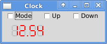
sim -init {
    set timer 0
    set modeBtn 0
    set upBtn 0
    set dnBtn 0
    set segments [list]
    set digit {{1 0 9 0} {10 1 10 9} {10 11 10 19} {1 20 9 20} {0 11 0 19}
            {0 1 0 9} {1 10 9 10}}
    set minsColour red
    set hrsColour red

    # read status callback function
    proc readStatCb {addr val} {
        global timer modeBtn upBtn dnBtn
        set rv [expr {$modeBtn | $upBtn << 1 | $dnBtn << 2}]
        incr timer
        if {$timer == 200} {
            set rv [expr {$rv | 0x80}]
            set timer 0
        }
        return $rv
    }

    # write display callback function
    proc writeDispCb {addr val} {
        global minsColour hrsColour
        if {$addr == [addr ctrlReg]} {
            set minsColour red
            set hrsColour red
            if {$val == 1} {
                set hrsColour darkred
            }
            if {$val == 2} {
                set minsColour darkred
            }
        }
        setDigit 3 [var lsMinutesReg] $minsColour
        setDigit 2 [var msMinutesReg] $minsColour
        setDigit 1 [var lsHoursReg] $hrsColour
        setDigit 0 [var msHoursReg] $hrsColour
        return $val
    }

    # offset position by x and y
    proc offsetPos {pos x y} {
        lassign $pos x1 y1 x2 y2
        incr x1 $x
        incr y1 $y
        incr x2 $x
        incr y2 $y
        return [list $x1 $y1 $x2 $y2]
    }

    # set digit number (0 to 3) to hexCode
    proc setDigit {num hexCode colour} {
        set i [expr {$num * 7}]
        for {set j 0} {$j < 7} {incr j} {
            set c [expr {$hexCode & 0x1 ? $colour : "gray"}]
            .disp itemconfigure [lindex $::segments $i] -fill $c
            set hexCode [expr {$hexCode >> 1}]
            incr i
        }
    }

    # build gui
    package require Tk
    wm title . Clock
    wm protocol . WM_DELETE_WINDOW exit
    ttk::checkbutton .modeBtn -text Mode -variable modeBtn
    ttk::checkbutton .upBtn -text Up -variable upBtn
    ttk::checkbutton .dnBtn -text Down -variable dnBtn
    tk::canvas .disp -width 200 -height 40
    grid .modeBtn .upBtn .dnBtn
    grid .disp - -
    foreach xpos {20 35 55 70} {
        foreach l $digit {
            lappend segments [.disp create line [offsetPos $l $xpos 10] \
                    -width 2 -fill gray]
        }
    }
    .disp create line 49 30 51 30 -width 2 -fill red

    # callback functions for i/o registers
    readCb statReg readStatCb
    writeCb ctrlReg writeDispCb
    writeCb msHoursReg writeDispCb

    startSim
    vwait forever
For more details, see http://www.p-code.org/clock_example.html
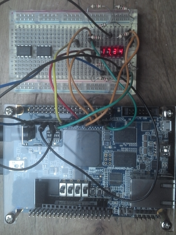
Once the assembler code has been simulated, it can be used with a reasonably high level of confidence that it will work first time in hardware. Indeed that is what happened. The image below shows a breadboard lashup using a rather nice old style bubble 7-segment display, connected to an Altera FPGA dev board.
Jorge - 2016-10-14 22:02:56
do you have plans to share the actual Tcl assembler/simulator?
pdt Yes, I'll make the source available, once it's in a more complete state.
chw shortly after: would you Jorge please contact me by private email?
Jorge says: could not find your email address, but mine is on my personal page on this wiki...