Snippets Physics Concepts Quantum
- Index for Snippets Physics Concepts Quantum
- Introduction
- Core Functionality
- Circuit Representation
- Design Considerations
- Playground V9
- Educational Applications
- Table 1: Concepts Quantum Circuit Visualization
- Table 2: Selected Key Symbols for Examples of Quantum Circuit Printouts
- Page Is Under Development
- Appendix Code
- 1. Expanded Toy for Pro of print_quantum_circuit
- Output from Playground V9
- Example usages in Playground V9
- Added Automatic Dump of Examples, Using ActiveState
- More Testing Examples
- Hidden Comments Section
- Program Change Log
Index for Snippets Physics Concepts Quantum
Preface
gold 2/3/2026. Here are some simple snippets for numerical methods. The goal is to use Tcl's minimalism as a learning tool. Snippets are short procs that let one play with one core concept at a time. All snippets are Playground V9 safe. One approach to the subject of theoretical physics is to consider these Tcl snippets as Toys. Some snippets here are listed as Toys. These Tcl procs are tiny entry points into theoretical physics. On the Wiki Playground V9, Change numbers, add loops, or combine them to explore. Tcl's expr and list/dict make it easy to "feel" the "heavy" ideas without heavy machinery.
The quantum circuit tool only visualizes circuit structure, whereas no state vector simulation, probabilities, or actual measurement outcomes are derived. The example tool is not a full quantum emulator. Meaning, limited scope for tutorial purposes.
Advisor requests similar to previous snippets, but on topic of quantum computing circuits. The Ideas Seemed to work, but maybe drawbacks?
Introduction
A quantum circuit is the basic model for performing computations in quantum computing, much like a classical digital circuit uses logic gates on bits. Here, a simplified quantum circuit consists of a sequence of quantum gates applied to qubits. Qubits are quantum bits that can exist in superposition. The examples include and follow measurements to extract classical results. The diagrams provide a clear, visual way to represent quantum algorithms. These are a step-by-step sequence of operations from left to right. Such that time flows horizontally and each horizontal layer (with "spaces") is tracking one qubit.
Visualizing these Quantum circuits using simple ASCII art in Tcl is especially helpful for beginners. Because pure Tcl requires no specialized software, graphical tools, or simulators. The printout is just plain text that runs instantly in any Tcl environment, including lightweight playgrounds or terminals. This low-barrier approach lets newcomers quickly experiment, modify, and "see" how gates like Hadamard or CNOT transform states. The Toy is intended to help build intuition about concepts like superposition and quantum entanglement. The Toy is a focus on the underlying physics without getting bogged down in setup, syntax of complex frameworks, or visual overload from full GUI renderers.
Body
This TCL program provides a pure ASCII quantum circuit visualization tool designed for educational environments. The TCL code creates readable quantum circuit diagrams using only standard ASCII characters. Standard ASCII characters make it compatible with basic text editors and ensuring portability across different systems without requiring special Unicode support.
Core Functionality
The central procedure, print_quantum_circuit, accepts a circuit description and renders it as a horizontal ASCII diagram. Each qubit appears on its own line or layer. For the examples selected, there may be as many as three layers. Each qubit or layer is initialized in the ground state |0>. The quantum gates and timed operations are flowing left to right across time steps. The visualization uses dashes to represent quantum spaces connecting and in line with sequential operations on each qubit.
Circuit Representation
The circuit input format uses a nested list structure where each gate operation consists of a gate name followed by qubit indices. Single-qubit gates like Hadamard (H), Phase (S), and Measurement (M) operate on individual qubits. The parameters display as bracketed symbols along the layer. Two-qubit gates like CNOT show vertical connections between control and target qubits. The displays are using 'o' for the control point and 'X' for the target operation, with vertical bars connecting intermediate qubits when the gate spans non-adjacent positions.
Design Considerations
The implementation carefully avoids problematic characters that might trigger TCL substitution issues. Gate symbols are constructed through safe string concatenation rather than direct bracket insertion. In a convention for the example diagrams, Wide spaces are shown with extended dash sequences. The dashed line as spaces in the example ensure the circuit structure remains visible. For the student examples, the spaces are rendered in environments with rendering quirks or formatting limitations on text. The design prioritizes readability for students with visual impairments by maintaining clear spacing and simple character choices suitable for large font display.
Playground V9
Playground V9 is the browser‑based Tcl/Tk console attached to the Tclers’ Wiki that lets you paste and run Tcl scripts interactively in a cloud session, without installing Tcl locally. It is used across “Snippets Physics Concepts” pages as the standard environment for short educational “toy” procs, with the constraint that all output must be strict ASCII.
To run the quantum‑circuit snippets there, a simple workflow is:
Open the Tclers’ Wiki page in a browser and use the “Playground” menu to launch a Tcl Playground V9 console in a separate tab or window.
Copy the entire tcl code block that defines quantum_circuit (and add any test circuits) from the wiki page, then paste it into the Playground console so that all proc definitions are loaded at once. Note: parsing, have to paste and copy code block onto the little clipboard tab, select all, windows copy to w. clipboard, and then use the paste command on the Playground headboard.
Extra Note. The clipboard tab on P9 is your only friend: Browser → little clipboard icon → select-all → Ctrl+C → headbar Paste button.
Press Enter to execute the pasted block; you should see any initial puts test messages confirming that the proc is defined and the console is working.
At the (tcl) prompt, call the proc with a circuit and qubit count, for example: quantum_circuit { {H 0} {S 0} {H 0} {M 0} } 1 to render the phase‑kickback example on one qubit, or quantum_circuit { {H 0} {CNOT 0 1} } 2 to see the Bell‑state circuit.
Caution: Bell state in 7 keystrokes: {H 0} {CNOT 0 1} 2. Entanglement achieved faster than your coffee cools.
Caution: Beware the refresh button. It wipes the slate clean.
To experiment, edit the circuit list directly at the prompt (change gate order, add M gates, swap CNOT control/target) and re‑run the command; as long as you avoid non‑ASCII characters in any puts strings, Playground V9 will render the ASCII diagrams reliably.
Ultimate playground enlightenment: The fastest way to learn quantum gates is to break them in ASCII, what tap should have been right, and stare at the wreckage until it makes sense.
Note. Empty spaces are shown as dashed lines in printout, "\---".
Educational Applications
The program demonstrates four canonical quantum circuit patterns. The superposition example shows a single Hadamard gate creating quantum superposition. The Bell state circuit combines Hadamard and CNOT gates to generate quantum entanglement. The measurement example extends the Bell state with explicit measurement operations on both qubits. The phase kickback demonstration illustrates how phase gates interact with Hadamard transformations, a fundamental concept in quantum algorithms.
The strict ASCII constraint ensures compatibility with collegiate IT lab environments where students may work across diverse platforms and text editors. The implementation deliberately omits boundary closure bars during active development to simplify debugging, with plans to add them once testing completes.
Table 1: Concepts Quantum Circuit Visualization
| Index No. | Example Name | Circuit List (Tcl) | Qubits | Rendered Output (Playground style) | Notes | Notes | |
|---|---|---|---|---|---|---|---|
| 1 | Superposition (Hadamard) | {{H 0}} | 1 | q0: | 0>---H------ | Creates equal superposition from !0⟩. Basic building block of most algorithms. | 1 layer shown |
| 2 | Bell state (max entanglement) | {{H 0} {CNOT 0 1}} | 2 | q0: | 0>---H------ o-----<br>q1: | 0>------------ X | Produces maximally entangled pair (Φ⁺ = (!00⟩ + !11⟩)/√2). Illustrates entanglement. 2 layers shown. |
| 3 | Bell state + measurement | {{H 0} {CNOT 0 1} {M 0} {M 1}} | 2 | q0: | 0>---H------ o----- M <br>q1: | 0>------------ X M | Same as above, but with final measurements (simulates typical experiment end). 2 layers shown |
| 4 | Simple phase kickback / interference | {{H 0} {S 0} {H 0} {M 0}} | 1 | q0: | 0>---H------S------H---M | H–phase–H sequence. Shows how relative phase affects interference (basis for Deutsch–Jozsa, phase kickback). | |
| 5 | Bit-flip error + correction toy | {{X 0} {H 0} {M 0}} | 1 | q0: | 0>---X------H------ M | Applies bit flip then Hadamard → measures in X basis. Useful for teaching Pauli errors. | |
| 6 | Two Hadamards (back to original) | {{H 0} {H 0}} | 1 | q0: | 0>---H------H------ | Demonstrates that Hadamard is its own inverse (unitary property). | |
| 7 | Phase gate sequence (S–T–S†) | {{S 0} {T 0} {S 0}} | 1 | q0: | 0>---S------T------S------ | Builds more complex phases (T = phase π/4). Precursor to universal gate sets. | |
| 8 | Measurement only (trivial circuit) | {{M 0}} | 1 | q0: | 0>--- M | Baseline: measuring !0⟩ always gives 0 (certainty). Good for testing measurement output. | |
| 9 | Empty circuit (just Empty spaces) | {} | 2 | q0: | 0>----------<br>q1: | 0>---------- | Shows idle qubits / baseline diagram. Useful for testing proc defaults. 2 layers shown. |
| 10 | Three-qubit GHZ state preparation | {{H 0} {CNOT 0 1} {CNOT 1 2}} | 3 | q0: | 0>---H------ o----- o-----<br>q1: | 0>------------ X | <br>q2: !----0>--------------- X Creates GHZ state (!000⟩ + !111⟩)/√2. Classic multi-qubit entanglement demo. 3 layers shown. |
Note. Empty spaces are shown as dashed lines, "\---". For the examples, each additional qubit adds an extra layer and up to 3 layers may be shown in the selected examples. Some of the diagram symbols and layer text are conflicting with reserve characters in the Wiki table formatting, "\|" and "\%". Some examples have extension of measurement, multiple states or alternate displays, which tried to show. Not all is simple, in land of Oz! Joke!
Table 2: Selected Key Symbols for Examples of Quantum Circuit Printouts
| Index No. | Abbreviation / Symbol | Full Name / Gate | Qubits | Notes | Notes |
|---|---|---|---|---|---|
| 1 | CNOT | Controlled-NOT (Controlled-X, CX) | 2 | Two-qubit entangling gate; flips target if control is | 1⟩. Core for Bell states, GHZ, most entanglement in examples (e.g., Bell, GHZ). Rendered with 'o' on control, 'X' on target. |
| 2 | H | Hadamard | 1 | Creates equal superposition ( | 0⟩ → (!0⟩ + !1⟩)/√2). Most common single-qubit gate; its own inverse (H² = I). Basis for many examples (superposition, Bell, GHZ, phase kickback). |
| 3 | I | Identity | 1 | Does nothing (placeholder or no-op). Not shown in examples but implicit in idle wires ('---'). | |
| 4 | M | Measurement (in Z basis) | 1 | Collapses qubit to classical bit (0 or 1); often ends circuits. Used in measurement examples; always | 0⟩ → 0 without prior gates. |
| 5 | S | Phase gate (S = Z^{1/2}) | 1 | Adds π/2 phase to | 1⟩ (S = [1,0],[0,i]). Used in phase sequences and kickback demos. |
| 6 | S† (or Sdg, S†) | Inverse Phase gate | 1 | Conjugate transpose of S ([1,0],[0,-i]); undoes S. Not in examples but common in circuits needing S inverse. | |
| 7 | T | T gate (π/4 phase) | 1 | Adds π/4 phase to | 1⟩ ([1,0],[0,exp(iπ/4)]). Non-Clifford; key for universal gate sets. Shown in phase gate sequence example. |
| 8 | T† (or Tdg) | Inverse T gate | 1 | Conjugate of T; common in approximation of other rotations. Not directly in examples. | |
| 9 | X | Pauli-X (bit-flip, NOT) | 1 | Flips !0⟩ !1⟩ ([0,1],[1,0]). Used in bit-flip error toy example. | |
| 10 | Y | Pauli-Y | 1 | Bit-flip + phase ([0,-i],[i,0]). Less common in basic demos but part of Pauli group. | |
| 11 | Z | Pauli-Z (phase-flip) | 1 | Adds π phase to | 1⟩ ([1,0],[0,-1]). Basis for phase gates (S = √Z, etc.). |
Note. Some of the diagram symbols and layer text are conflicting with reserve characters in the Wiki table formatting, "\|" and "\%".
Page Is Under Development
This page is under development. Comments are welcome, but please load any comments in the comments section at the bottom of the page. Please include your wiki MONIKER and date in your comment with the same courtesy that I will give you. Aside from your courtesy, your wiki MONIKER and date as a signature and minimal good faith of any internet post are the rules of this TCL-WIKI. Its very hard to reply reasonably without some background of the correspondent on his WIKI bio page. Thanks, gold 5Jan2026
Screenshots Section
figure 1.
Snippets Physics Concepts Quantum double
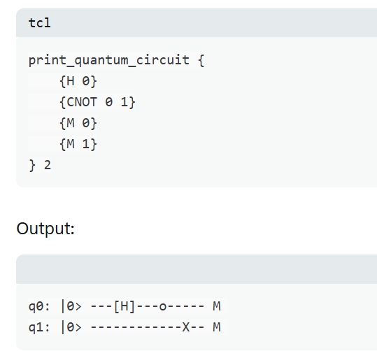
figure 2.
Snippets Physics Concepts Quantum bell
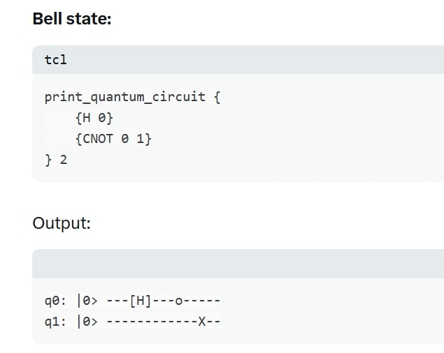
figure 3.
Snippets Physics Concepts Quantum example
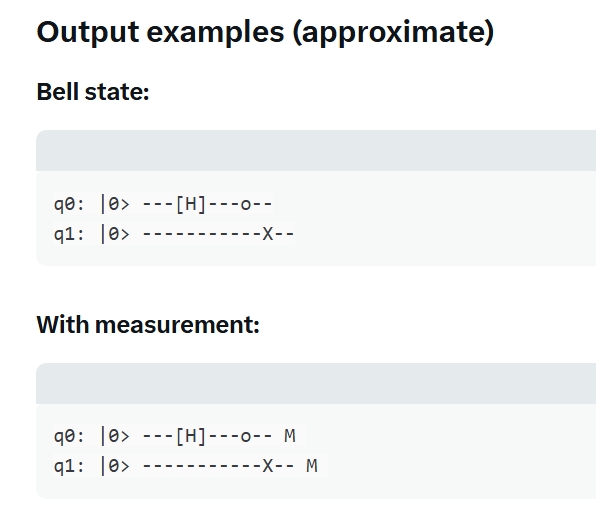
figure 4.
Snippets Physics Concepts Quantum printout2
Working printout from Playground V9 showing several examples, off the cuff.
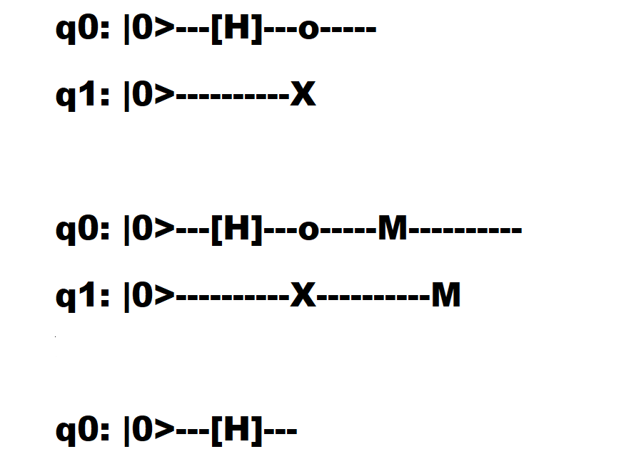
figure 5.
Snippets Physics Concepts Quantum printout2
Working printout from a Python Version showing several examples, off the cuff.
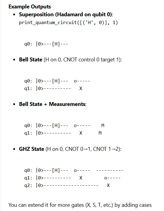
**** figure. QUANTUM CIRCUIT VISUALIZATION OVERVIEW ****

+----------------------------------------------------------------------------------+
| QUANTUM CIRCUIT VISUALIZATION - EDUCATIONAL TOY                                  |
|                                                                                  |
|    Features:                                                                     |
|      • Pure ASCII output (strict 7-bit, Playground V9 safe)                      |
|      • Time flows left to right                                                  |
|      • Each horizontal line = one qubit                                          |
|      • Gates shown as [H], [S], [T], [X], M (measurement)                        |
|      • CNOT shown with o (control) ── X (target)                                 |
|      • Double-hatch borders (## ... ##) for clarity                              |
|                                                                                  |
|    Goal: Build intuition for superposition, entanglement,                        |
|          and measurement without heavy simulators                                |
+----------------------------------------------------------------------------------+

**** figure. SINGLE QUBIT SUPERPOSITION (HADAMARD GATE) ****

+----------------------------------------------------------------------------------+
| 1. SUPERPOSITION EXAMPLE                                                         |
|                                                                                  |
| ## q0: |0> ---[H]--- ##                                                          |
|                                                                                  |
|    Operation: Apply Hadamard gate to qubit 0                                     |
|    Result: Creates equal superposition                                           |
|            |0⟩  →  (|0⟩ + |1⟩)/√2                                                |
|                                                                                  |
|    Classic first step in almost every quantum algorithm                          |
+----------------------------------------------------------------------------------+

**** figure. BELL STATE ENTANGLEMENT (H + CNOT) ****

+----------------------------------------------------------------------------------+
| 2. BELL STATE (MAXIMALLY ENTANGLED EPR PAIR)                                    |
|                                                                                  |
| ## q0: |0> ---[H]------o----- ##                                                 |
| ## q1: |0> ------------X----- ##                                                 |
|                                                                                  |
|    Steps:                                                                        |
|      1. Hadamard on qubit 0 → superposition                                      |
|      2. CNOT (control 0, target 1) → entanglement                                |
|                                                                                  |
|    Final state: (|00⟩ + |11⟩)/√2   (Bell Φ⁺ state)                              |
|    Classic demonstration of quantum entanglement                                 |
+----------------------------------------------------------------------------------+

**** figure. BELL STATE WITH MEASUREMENT ****

+----------------------------------------------------------------------------------+
| 3. BELL STATE + MEASUREMENT                                                      |
|                                                                                  |
| ## q0: |0> ---[H]------o-----M--- ##                                             |
| ## q1: |0> ------------X-----M--- ##                                             |
|                                                                                  |
|    Full experiment:                                                              |
|      Create entanglement → measure both qubits                                   |
|                                                                                  |
|    Expected result:                                                              |
|      Always get 00 or 11 together (perfect correlation)                          |
|    Demonstrates collapse and correlation in measurement                          |
+----------------------------------------------------------------------------------+

**** figure. PHASE KICKBACK EXAMPLE ****

+----------------------------------------------------------------------------------+
| 4. PHASE KICKBACK TOY CIRCUIT                                                    |
|                                                                                  |
| ## q0: |0> ---[H]------[S]------[H]---M--- ##                                    |
|                                                                                  |
|    Sequence: H → S (phase) → H → Measure                                         |
|                                                                                  |
|    Shows how phase on one qubit affects interference                             |
|    Important building block for:                                                 |
|      • Deutsch–Jozsa algorithm                                                   |
|      • Phase estimation                                                          |
|      • Many quantum algorithms                                                   |
+----------------------------------------------------------------------------------+

**** figure. GHZ STATE (THREE-QUBIT ENTANGLEMENT) ****

+----------------------------------------------------------------------------------+
| 5. GHZ STATE PREPARATION (3 QUBITS)                                             |
|                                                                                  |
| ## q0: |0> ---[H]------o-------------o----- ##                                   |
| ## q1: |0> ------------X-------------|----- ##                                   |
| ## q2: |0> --------------------------X----- ##                                   |
|                                                                                  |
|    Creates GHZ state: (|000⟩ + |111⟩)/√2                                         |
|    True multi-qubit entanglement                                                 |
|    Foundation for quantum error correction and teleportation studies             |
+----------------------------------------------------------------------------------+

**** figure. QUANTUM CIRCUIT SYMBOL LEGEND ****

+----------------------------------------------------------------------------------+
| QUANTUM CIRCUIT SYMBOL LEGEND                                                    |
|                                                                                  |
|    [H]   → Hadamard gate          (superposition)                                |
|    [S]   → Phase gate (π/2)                                                      |
|    [T]   → T gate (π/4 phase)                                                    |
|    [X]   → Pauli-X (bit flip)                                                    |
|    M     → Measurement (Z basis)                                                 |
|    o-----                                                        |
|         X   → CNOT (controlled-NOT)                                              |
|    ---   → Idle wire / time step                                                 |
|    ##    → Diagram borders (for clarity in wiki/playground)                      |
|                                                                                  |
|    Time flows left → right                                                       |
+----------------------------------------------------------------------------------+

**** figure. QUANTUM CIRCUIT SUMMARY ****

+----------------------------------------------------------------------------------+
| EDUCATIONAL SUMMARY                                                              |
|                                                                                  |
|    This pure-Tcl ASCII quantum circuit toy lets students:                        |
|      • Visualize superposition and entanglement                                  |
|      • Experiment with gate sequences instantly                                  |
|      • Understand measurement collapse                                           |
|      • Run in Playground V9 without any extra tools                              |
|                                                                                  |
|    Perfect for beginners and collegiate labs                                     |
|    Focuses on intuition rather than heavy simulation                             |
+----------------------------------------------------------------------------------+
References
- Snippets Physics Concepts Toy
- Snippets Physics Concepts Minimalism
- Zero Handling Workarounds
Appendix Code
Appendix TCL Programs and Scripts
1. Expanded Toy for Pro of print_quantum_circuit
This is a draft, still debugging on Playground V9.
# Tcl
# Educational quantum_circuit_ascii Prototype (strict ASCII only) V5
# Human Readable Names Employed Edition
# Goal: Make relationships and calculations easier to read and teach
# for Tool Control Language Programs
# Compatible with Tcl/Tk 8.6+
# TCL source code follows
# Written for Windows 11 on ActiveState TCl
# Working on TCL Playground V9, strict ASCII only
# Optimized for collegiate IT lab environments
# Working under TCL version 8.6
# Added Automatic Dump of Examples, Using ActiveState
# Added temp double hatch border.
# Complex math calculations up to 3 units computer time
# Wait for complete calculations before saving files.
# TCL club, 02/3/2026
#
# ----------------------------------------------------------------------------
#  Educational  Prototype (strict ASCII only)
# For Tcl 8.6 or later
# Designed for large font / weak eyes: simple text, clear comments
console show
# print_quantum_circuit --
# Renders ASCII quantum circuit with wide forced dashed line as
# temp space separator to survive Playground quirks
#
proc print_quantum_circuit {circuit {num_qubits 2}} {
    # Initialize diagram lines for each qubit
    set qubit_diagram_lines {}
    for {set qubit_index 0} {$qubit_index < $num_qubits} {incr qubit_index} {
        lappend qubit_diagram_lines [list "q${qubit_index}: |0>" ""]
    }

    # ─────────────────────────────────────────────────────────────────────────────
    # Process each gate/time-step
    # ─────────────────────────────────────────────────────────────────────────────
    foreach gate_step $circuit {
        set gate_name   [lindex $gate_step 0]
        set gate_args   [lrange $gate_step 1 end]

        # Default wide idle wire
        set column_symbols [lrepeat $num_qubits "----------"]

        if {$gate_name eq "CNOT"} {
            set control_qubit [lindex $gate_args 0]
            set target_qubit  [lindex $gate_args 1]

            lset column_symbols $control_qubit "  o-----  "
            lset column_symbols $target_qubit  "   X      "

            set lower [expr {min($control_qubit, $target_qubit)}]
            set upper [expr {max($control_qubit, $target_qubit)}]
            for {set mid [expr {$lower + 1}]} {$mid < $upper} {incr mid} {
                lset column_symbols $mid "   |      "
            }

        } elseif {$gate_name eq "M"} {
            set measured_qubit [lindex $gate_args 0]
            lset column_symbols $measured_qubit "    M     "

        } else {
            # Single-qubit gate: safe construction to avoid [ ] substitution
            set operated_qubit [lindex $gate_args 0]
            set gate_symbol    [string toupper [string range $gate_name 0 0]]
            # Build string safely: concat pieces
            set gate_block [concat "---" "\[" $gate_symbol "\]" "---"]
            lset column_symbols $operated_qubit $gate_block
        }

        # Append column to each line
        for {set qubit_index 0} {$qubit_index < $num_qubits} {incr qubit_index} {
            set existing_line [lindex $qubit_diagram_lines $qubit_index]
            lset qubit_diagram_lines $qubit_index \
                [concat $existing_line [lindex $column_symbols $qubit_index]]
        }
    }

    # ─────────────────────────────────────────────────────────────────────────────
    # Add left + right double-hatch borders (## ... ##) – pure ASCII
    # ─────────────────────────────────────────────────────────────────────────────
    for {set i 0} {$i < $num_qubits} {incr i} {
        set line [lindex $qubit_diagram_lines $i]

        # Join columns first so wires stay connected
        set rendered [join $line ""]

        # Add double hatch borders with small spacing
        # set new_rendered " ##${rendered}## "
        # added patch, shows alternate look
        set new_rendered " ## ${rendered} ## "
        # Store as single string per line
        lset qubit_diagram_lines $i [list $new_rendered]
    }

    # Output the diagram
    foreach diagram_line $qubit_diagram_lines {
        puts [lindex $diagram_line 0]
    }
    puts ""   ;# blank separator
}

# ─────────────────────────────────────────────────────────────────────────────
# Automatic examples when file is sourced / run directly
# ─────────────────────────────────────────────────────────────────────────────

if { [info script] eq $::argv0 } {   ;# only run examples if script is main file

    puts "\nEducational quantum circuit examples"
    puts "--------------------------------------------\n"

    puts "1. Superposition:"
    print_quantum_circuit {{H 0}} 1

    puts "2. Bell state (EPR pair):"
    print_quantum_circuit {
        {H 0}
        {CNOT 0 1}
    } 2

    puts "3. Bell state + both measured:"
    print_quantum_circuit {
        {H 0}
        {CNOT 0 1}
        {M 0}
        {M 1}
    } 2

    puts "4. Phase kickback toy example:"
    print_quantum_circuit {
        {H 0}
        {S 0}
        {H 0}
        {M 0}
    } 1

    puts "5. Two-qubit controlled-phase (example):"
    print_quantum_circuit {
        {H 0}
        {H 1}
        {CNOT 0 1}
        {S 1}
        {CNOT 0 1}
    } 2
}
Output from Playground V9
(tcl) 14 %
(tcl) 14 % # Expected / hoped-for output in Playground:
(tcl) 15 % # q0: |0> ---[H]------[S]------[H]------ M -------

seems to work now.

There is >>>NO<<< closure bar on the left and right boundary.
May install closure bar  when debugging finished.
% # ─────────────────────────────────────────────────────────────────────────────
(tcl) 6 % # Test:  phase kickback example
(tcl) 7 % # ─────────────────────────────────────────────────────────────────────────────
(tcl) 8 %
(tcl) 8 % puts "Simple phase kickback toy circuit:"
Simple phase kickback toy circuit:
(tcl) 9 % print_quantum_circuit {>     {H 0}
>     {S 0}
>     {H 0}
>     {M 0}
> } 1
q0: |0>---[H]------[S]------[H]---M
Empty spaces are shown as dashed lines in printout, "\---".
Example usages in Playground V9
# -----------------------
# Example usages
# -----------------------

puts "1. Superposition:"
print_quantum_circuit {{H 0}} 1
# > q0: |0> ---[H]---

puts "2. Bell state circuit:"
print_quantum_circuit {
    {H 0}
    {CNOT 0 1}
} 2
# > q0: |0> ---[H]---o--
# > q1: |0> -----------X--

puts "3. With measurement:"
print_quantum_circuit {
    {H 0}
    {CNOT 0 1}
    {M 0}
    {M 1}
} 2
# > q0: |0> ---[H]---o-- M
# > q1: |0> -----------X-- M

puts "4. Simple phase kickback toy:"
print_quantum_circuit {
    {H 0}
    {S 0}
    {H 0}
    {M 0}
} 1

q0: |0>---[H]------[S]------[H]---M
Added Automatic Dump of Examples, Using ActiveState
Educational quantum circuit examples
--------------------------------------------

1. Superposition:
 ##q0: |0>---[H]---##

2. Bell state (EPR pair):
 ##q0: |0>---[H]---o-----##
 ##q1: |0>----------X##

3. Bell state + both measured:
 ##q0: |0>---[H]---o-----M----------##
 ##q1: |0>----------X----------M##

4. Phase kickback toy example:
 ##q0: |0>---[H]------[S]------[H]---M##

5. Two-qubit controlled-phase (example):
 ##q0: |0>---[H]-------------o---------------o-----##
 ##q1: |0>-------------[H]---X---[S]---X##
More Testing Examples
One-qubit classics (phase & measurement weirdness)
Phase kickback demo ( original, but worth repeating): print_quantum_circuit { {H 0} {S 0} {H 0} {M 0} } 1 & → Shows how phase on control qubit appears before measurement.
T gate sandwich (extra phase = π/4): print_quantum_circuit { {H 0} {T 0} {H 0} {M 0} } 1 & Wisdom: T is the laziest way to get off the Bloch equator.
Full S† → Z → S cycle check: print_quantum_circuit { {H 0} {S 0} {Z 0} {S 0} {H 0} {M 0} } 1 & → Should behave like plain Hadamard + measure (Z cancels the two S gates).
Two-qubit entanglement & teleportation?
liteReverse Bell (swap roles): print_quantum_circuit { {H 1} {CNOT 1 0} } 2 &
→ Entangles with target on 0 instead — same state, different drawing. GHZ state (three-way W not included):
print_quantum_circuit { {H 0} {CNOT 0 1} {CNOT 0 2} } 3 & → The minimalist route to “all qubits agree… eventually”.
Super-dense coding sender side (one half): print_quantum_circuit { {H 0} {CNOT 0 1} {X 0} {Z 0} } 2 & → Encode 00/01/10/11 by doing nothing/X/Z/XZ on Alice’s qubit. --- Three+ qubits — small algorithms & tricks
Toffoli test (CCNOT — if supported; many ASCII drawers alias it CCX):
print_quantum_circuit { {H 0} {H 1} {CCNOT 0 1 2} {M 2} } 3 & → Turns |00⟩|0⟩ → |00⟩|0⟩ and |11⟩|0⟩ → |11⟩|1⟩ after H on controls. Swap via three CNOTs (old-school wire cross):
print_quantum_circuit { {CNOT 0 1} {CNOT 1 0} {CNOT 0 1} } 2 & → Swaps state of qubit 0 1 without temp qubit. Classic wire-saver.
Bit-flip code encoding step: print_quantum_circuit { {H 1} {CNOT 1 0} {H 2} {CNOT 2 0} } 3 & → Encodes logical |0⟩L → |000⟩ + logical |1⟩L → |111⟩ (repetition code).
Note. Added some ampersands "\&" to separate text run together and jumble. Qubit No. are integers in deck.
gold 01/30/2026. Added categories, so can find message in Wiki.
Hidden Comments Section
Program Change Log
gold 2/3/2025. Testing, encountered initial difficulty in saving work? Long code blocks with or unmatched wiki markup can sometimes confuse the Tcl Wiki formatting engine, especially if fences are not balanced or a line begins with markup it treats specially.
gold 2/4/2025. Made changes to write-up. Some of the diagram symbols are conflicting with reserve characters in the Wiki table formatting, "\|" and "\%".
gold 2/4/2025. Made changes to deck. Some of the blank spaces in diagrams are either not honored across transfer to web text editors or spaces collapse on transfer. Not sure how to fix, other than old-fashioned "hard wire" fixes as ugly dashed lines, using engr. slang. Printouts with Left Arrow symbol and other Unicode symbols are aborting Playground V9 displays, normal chan fix ineffective and not sure why. Have deadlines here and chose to limp ahead.
gold 2/4/2025. logical on time. >> time <<< flow is left → right in basically every practical quantum circuit diagram, you'll encounter. It's a convention, but a very consistent one. The closest thing to "quantum wires" in diagrams is just elegant abstraction — no copper or gold spool required for the magic to happen. If you're visualizing circuits in Tcl/Python (like we talked about before), those diagram lines are exactly that: logical flow of time, not physical metal. In quantum computing, "quantum wires" sometimes refer to: Nanowires used to host Majorana zero modes (exotic quasiparticles) for topological qubits. Microsoft's approach uses semiconductor nanowires coated with superconductor like aluminum to try making more error-resistant qubits. Shucks! The hardware store is all sold out of "quantum wire" for this winter. Joke!
The "wires" you see in quantum circuit diagrams (those horizontal lines connecting gates like H, X, CNOT, etc.) are purely abstract. "Diagram Lines/Wires" or dashed lines here just represent the flow of time and the logical progression of a qubit's state. Physically, there's no literal wire carrying a current from one gate to the next in most quantum hardware. The qubit stays put (or is trapped), and "gates" are applied by hitting it with precise microwave pulses, lasers, or magnetic fields at the right moments. The input "wire" is basically "wait until time t, then apply this operation." Using dashed line convention here.
gold 2/4/2025. Tasks 1 and 2 have been completed and module/changes added, ref emails. Thanks for consideration, remaining chores for me is to develop / check testcases and "beautify" code to best practices.
gold 2/4/2025. Added Automatic Dump of Examples, Using ActiveState. Added temp double hatch border, ##.
gold 2/6/2025.
        # set new_rendered " ##${rendered}## "
        # added patch, shows alternate look
set new_rendered " ## ${rendered} ## "Please place any comments here with your wiki MONIKER and date, Thanks.gold 1/30/2026
Note. Testing computer methods and computer programs, maybe wrong numbers.
| Category Numerical Analysis | Category Toys | Category Calculator | Category Mathematics | Category Example | Toys and Games | Category Games | Category Application | Category GUI |