Thales Theorem Demo - Right Triangles In a Semi-circle
uniquename - 2013dec03
I am interested in providing Tk GUI's that demonstrate various mathematical 'truths' in an animated and/or interactive fashion.
Near the bottom of my 'bio' page uniquename, I have listed about 30-plus math demos (geometry, number theory, sequences-and-series, etc.) that I would eventually like to complete (in my old age).
On this page, I present the first of my 'geometry-fact demos' --- and in the process I have devised a set of 'draw' procs that will help me do drawings in 'world coordinates' --- and handle the conversion to pixels, on a Tk canvas, 'in the background'. (See the 'Some Features of the Code' section below for some explanation of this 'hiding-of-the-pixel-calcs' technique.)
I have chosen as a first 'geometry demo' a classic geometry theorem attributed to Thales [L1 ], circa 550 B.C. This theorem is often cited as one of the first known 'generalized' proofs in plane geometry. Thales is believed to have been a giant on whose shoulders Pythagoras, Euclid, and Archimedes stood.
Goals of the GUI
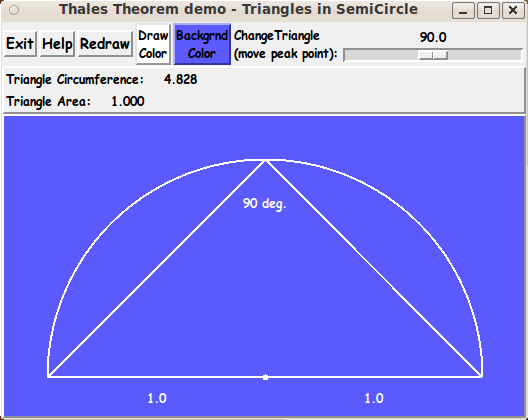
In this Tk script, I wanted to demonstrate the Thales theorem [L2 ] that says: The triangles inscribed in a semi-circle are all RIGHT triangles --- when one side of the triangles is coincident with the flat, diametral side of the semi-circle.
I wanted the GUI to use a Tk 'canvas' widget to show the semi-circle and a triangle inscribed within it. A 'scale' widget on the GUI may be used to allow the user to easily sweep through a family of triangles inscribed in the semi-circle.
In this implementation, I decided to display the diametral side of the semi-circle on the bottom side of the semi-circle, and the 'peak point' of the triangle(s) is to move along the arc of the semi-circle while the other two vertices of the triangle stay fixed at the ends of the diametral side (straight line-segment) of the semi-circle.
An additional goal of this GUI is to allow the canvas (and the geometry drawn within the canvas) to be easily resized if the GUI window is resized by the user.
Additional items to display on the GUI
Various numeric properties of the triangle could be displayed as the 'peak point' is moved along the circumference of the semi-circle. I decided to show the circumference of the triangle (sum of the lengths of the 3 sides) and the area of the triangle --- in a couple of 'label' widgets on the GUI.
Some Images of the GUI
Here are a couple of images of the GUI that I ended up with. The first image shows the GUI as it first appears.
And here is an image after:
1) changing the 'draw' and 'background' colors of the canvas items and the canvas,
2) resizing the window to a smaller size than the initial size, and
3) sliding the 'slider' of the 'scale' widget to a different setting from the initial setting.
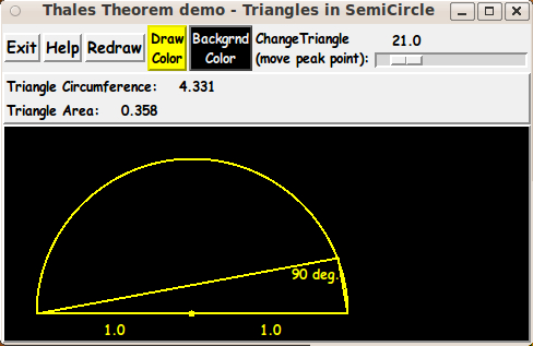
Note that there are 2 color buttons across the top of the GUI for assigning a color to canvas background and to the items drawn on the canvas.
Also note that there is a 'scale' widget on the GUI that allows the user to easily move the 'peak point' of the triangle(s) from one side of the semi-circle to the other.
The size of the semi-circle and triangle can be changed by resizing the window and clicking on the 'Redraw' button. The new size of the canvas widget is used to determine the new location and size of the semi-circle.
(The jaggies on the straight lines and the semi-circle arc MAY be nearly invisible if you try this script on a 'retina display', with monitor resolution on the order of 2000x1500 pixels --- more than 150 pixels per inch.)
---
Note that the color buttons call on a color-selector-GUI script to set those colors. You can make that color-selector Tk script by cutting-and-pasting the code from the page A non-obfuscated color selector GUI on this site.
The Code :
Below is the code that produced this GUI.
There are comments at the top of the code, in a section titled 'CAPTURING THE GUI IMAGE', that describe how one can 'capture' images produced by this GUI.
I follow my usual 'canonical' structure for Tk code, for this Tk script:
  0) Set general window & widget parms (win-name, win-position,
     win-color-scheme, fonts, widget-geometry-parms, win-size-control,
     text-array-for-labels-etc).

  1a) Define ALL frames (and sub-frames, if any).
  1b) Pack   ALL frames and sub-frames.

  2) Define & pack all widgets in the frames, frame by frame.
              Within each frame, define ALL the widgets.
              Then pack the widgets.

  3) Define keyboard and mouse/touchpad/touch-sensitive-screen 'event'
     BINDINGS, if needed.

  4) Define PROCS, if needed.

  5) Additional GUI initialization (typically with one or more of
     the procs), if needed.
This Tk coding structure is discussed in more detail on the page A Canonical Structure for Tk Code --- and variations.
This structure makes it easy for me to find code sections --- while generating and testing a Tk script, and when looking for code snippets to include in other scripts (code re-use).
I call your attention to step-zero. One new thing that I have started doing recently is using a text-array for text in labels, buttons, and other widgets in the GUI. This can make it easier for people to internationalize my scripts. I will be using a text-array like this in most of my scripts in the future.
Experimenting with the GUI
As in all my scripts that use the 'pack' geometry manager (which is all of my 100-plus Tk scripts, so far), I provide the four main pack parameters --- '-side', '-anchor', '-fill', and '-expand' --- on all the 'pack' commands for the frames and widgets.
That helps me when I am initially testing the behavior of a GUI (the various widgets within it) as I resize the main window.
I think I have found a good setting of the '-side', '-anchor', '-fill', and '-expand' parameters on the 'pack' commands for the various widgets of this GUI. In particular ...
The 'canvas' widget expands/contracts appropriately when the window size is changed --- and button and label widgets stay fixed in size and relative-location as the window size is changed.
If anyone wants to change the way the GUI configures itself as the main window size is changed, they can experiment with the '-side', '-anchor', '-fill', and '-expand' parameters on the 'pack' commands for the various widgets --- to get the widget behavior that they want.
Note: I have found that one can get some quite surprising self-changing movement of the slider-button on scale widgets if you allow a scale widget to expand and allow the window to expand. So you may want the scale widgets to stay fixed in length ('-fill none') and/or use '-expand 0' when packing scale widgets --- rather than using '-fill x -expand 1' with scale widgets and an expandable GUI window.
Additional experimentation: You might want to change the fonts used for the various GUI widgets. For example, you could change '-weight' from 'bold' to 'normal' --- or '-slant' from 'roman' to 'italic'. Or change font families.
In fact, you may NEED to change the font families, because the families I used may not be available on your computer --- and the default font that the 'wish' interpreter chooses may not be very pleasing.
I use variables to set geometry parameters of widgets --- parameters such as border-widths and padding. And I have included the '-relief' parameter on the definitions of frames and widgets. Feel free to experiment with those 'appearance' parameters as well.
Some features of the code
That said, here's the code --- with plenty of comments to describe what most of the code-sections are doing.
The main routine is the 'Redraw' proc. But that proc uses a set of 'draw' procs that allow the coder to work mostly in 'world coordinates' rather than 'pixel coordinates'.
The 'draw' procs have fairly descriptive names:
  mapping_for_wc2px
  Xwc2px
  Ywc2px
  draw_line_x1y1x2y2
  draw_arc_x1y1_degStart_degExtent
  draw_text_x1y1_center
  draw_point_x1y1_radiusPx
The input to all of these procs except the first one are 'world coordinates' rather than 'pixel coordinates'. And the only pixel coordinates input to the 'mapping_for_wc2px' proc are the pixel coordinates of the upper-left and lower-right corners of a rectangle on the canvas --- and those two points are usually taken to be the corners of the canvas --- (0,0) and (canvasWidthPx,canvasHeightPx).
The pixel calculations (to translate world coordinates to pixel coordinates) are 'hidden' in the 'Xwc2px' and 'Ywc2px' procs.
You can see the comments in the 'Redraw' proc for details on how the 'draw' procs are used to make the image on the canvas.
A few other procs are:
   set_draw_color        - for the 'DrawColor' button
   set_background_color  - for the 'BackgroundColor' button
   update_button_colors  - called by the set-color procs
   popup_msgVarWithScroll - called by the 'Help' button
It is my hope that the copious comments in the code will help Tcl-Tk coding 'newbies' get started in making GUI's like this. Without the comments --- especially in the 'Redraw' proc and the various 'draw' procs, the code would look like 'too much monkey business to be involved in', to quote Chuck Berry.
Without the comments, potential young Tcler's might be tempted to return to their iPhones and iPads and iPods --- to watch videos of 'news people' on various TV channels --- all of them repeating the same phrases that someone has provided to all of them.
Code for Tk script 'thalesTheorem_rightTriangles_inSemiCircle.tk' :
#!/usr/bin/wish -f
##+########################################################################
##
## SCRIPT: thalesTheorem_rightTriangles_inSemiCircle.tk
##
## PURPOSE: This Tk script is meant to demonstrate the Thales theorem that
## says: The triangles inscribed in a semi-circle (with one side
## of the triangles coincident with the flat, diametral side of
## the semi-circle) are all RIGHT triangles.
##
## METHOD: This GUI uses a Tk 'canvas' widget to show the semi-circle
## and a triangle inscribed within it. A 'scale' widget on the
## GUI allows the user to easily sweep through a family of
## triangles inscribed in the semi-circle.
##
## In this implementation,
## the diametral side of the semi-circle is displayed on the
## bottom side of the semi-circle, and the 'peak point' of the
## triangle(s) moves along the arc of the semi-circle while the
## other two vertices of the triangle stay fixed at the ends
## of the diametral side (line-segment) of the semi-circle.
##
## If the user clicks on a 'ShowProof' button, some extra lines and
## text are drawn on the canvas to indicate Thales' proof of the
## fact (the theorem) --- and a popup window appears with text
## that explains the proof.
##
## A goal of this GUI is to allow the canvas (and the geometry
## drawn within the canvas) to auto-resize if the GUI window
## is resized by the user.
##
##+######################################
## ADDITIONAL ITEMS TO DISPLAY (optional):
##
## Various numeric properties of the triangle can be displayed as the
## 'peak point' is moved along the circumference of the semi-circle
## --- such as the circumference of the triangle (sum of the lengths
## of the 3 sides), the area of the triangle, the 3 angles of the
## triangle (in degrees or radians), etc.
##
## Furthermore, eventually, various geometric properties of the
## triangle could be displayed on the canvas. For example, the
## 'centroid' of the triangle could be drawn as a point inside
## the triangle, and the centroid would move (be erased and re-drawn)
## as the 'peak point' of the triangle is moved by the user.
##
##+#########################
## PLANNED LAYOUT OF THE GUI:
##
## -----------------------------------------------------------------------------
## Thales Theorem demo - Triangles in a SemiCircle
## [window title]
## -----------------------------------------------------------------------------
##
## {Exit} {Help} {Redraw} {DrawColor} {BackgdColor} Change triangle: <------O----->
## (move peak point)
## X ShowProof {DotProduct}
##
## Triangle circumference: 4.331
## Triangle area: 0.358
## [These 'factoids' are shown in a stack of label widgets.]
##
## ---------------------------------------------------------------------------------
## | |
## | |
## | |
## | 'Canvas' for displaying the semicircle and the inscribed triangle --- |
## | and various proof lines and labels when the 'ShowProof' button is clicked. |
## | |
## | |
## | |
## | |
## | |
## ---------------------------------------------------------------------------------
##
## SKETCH CONVENTIONS for this GUI sketch:
##
## SQUARE-BRACKETS indicate a comment (not to be placed on the GUI).
## BRACES indicate a Tk 'button' widget.
## A COLON indicates that the text before the colon is on a 'label' widget.
## UNDERSCORES indicate a Tk 'entry' widget.
## CAPITAL-X indicates a Tk 'checkbutton' widget.
## CAPITAL-O indicates a Tk 'radiobutton' widget (if any).
##
## A LINE (HYPHENS or VERTICAL-BARS) WITH AN 'ARROW-HEAD' AT EACH END indicates
## a Tk 'scale' widget.
##
## A combination of VERTICAL-BAR CHARACTERS AND HYPHEN (or UNDERSCORE) CHARACTERS,
## that outline a RECTANGULAR SHAPE, are used to indicate either a Tk 'listbox' or
## a Tk 'canvas' widget or a Tk 'text' widget.
##
## SCROLL-BAR 'ARROW-HEADS' (for a 'listbox', 'canvas', or 'text' Tk widget)
## are drawn as follows:
##
## UP ARROW-HEAD is drawn with a CAPITAL-A.
## DOWN ARROW-HEAD is drawn with a CAPITAL-V.
## LEFT ARROW-HEAD is drawn with a LESS-THAN sign.
## RIGHT ARROW-HEAD is drawn with a GREATER-THAN sign.
##
## UP-and-DOWN ARROW-HEADS at the right/left of the box shape indicate
## a VERTICAL SCROLL-BAR there.
##
## LEFT-and-RIGHT ARROW-HEADS at the bottom/top of the box shape indicate
## a HORIZONTAL SCROLL-BAR there.
##
## The arrow-heads on a horizontal scrollbar are joined by hyphens, rather than
## underscores.
##
##+##################
## GUI WIDGET SUMMARY:
##
## This GUI will contain about:
##
## 6 'button' widgets
## 3 'label' widgets
## 0 'entry' widgets
## 1 'scale' widget
## 1 'checkbutton' widget
## 0 'radiobutton' widgets
## 1 'canvas' widget (with no x-y scrollbars)
## 0 'listbox' widgets
## 0 'text' widgets
##
##+################
## GUI DESCRIPTION:
##
## This script provides a Tk GUI with the following widgets.
##
## 1) There is an 'fRbuttons' frame to hold BUTTONS such as
## 'Exit' and 'Help' buttons --- as well as a 'Redraw'
## button.
##
## There is a SCALE widget that allows the user to move the
## 'peak point' of the triangle along the circumference of
## the semi-circle. The scale widget may be used to control
## an angle --- say from 0 to 180, or 1 to 179. This number (angle)
## is used to determine the x,y coordinates of the 'peak point'.
##
## 2) There is an 'fRcanvas' frame to contain a CANVAS widgets that
## holds the drawing of the semi-circle and the triangle(s).
##
## 3) Also an 'fRinfo' frame may be used to hold some LABEL widgets,
## to show properties of the triangle(s), such as circumference
## (sum of the lengths of the 3 sides) and area.
##
##+##################################
## METHOD USED to update the drawing:
##
## A set of drawing procs are used convert 'world coordinates' to
## pixel coordinates of the Tk canvas.
##
## The diametral side of the semi-circle is defined with center
## at 0,0 in 'world coordinates' --- and the end-points of the
## diameter are set to -1,0 and 1,0 in 'world coordinates'.
##
## Thus the semi-circle has 'unit radius', and the 'peak point' of
## each triangle, calculated in 'world coordinates', is
## the end-point of a radus extending from 0,0 to the (upper) arc
## of the semi-circle.
##
## The drawing procs are used to convert the 'world coordinates'
## to pixel coordinates of the Tk canvas and to draw lines and
## arcs. Some drawing procs are also provided to put some text items
## on the canvas, such as labels for vertices or values of angles.
##
## The names and descriptions of the drawing procs are below.
##
##+#######################
## CAPTURING THE GUI IMAGE:
##
## A screen/window capture utility (like 'gnome-screenshot'
## on Linux) can be used to capture the GUI image in a PNG
## or GIF file, say.
##
## If necessary, an image editor (like 'mtpaint' on Linux)
## can be used to crop the window capture image. The image
## could also be down-sized --- say to make a smaller image
## suitable for use in a web page or an email.
##
##+#######################################################################
## 'CANONICAL' STRUCTURE OF THIS CODE:
##
## 0) Set general window parms (win-name, win-position, win-color-scheme,
## fonts, widget-geom-parms, win-size-control, text-array-for-labels-etc).
##
## 1a) Define ALL frames (and sub-frames, if any).
## 1b) Pack the frames.
##
## 2) Define & pack all widgets in the frames, frame by frame.
## After all the widgets for a frame are defined, pack them in the frame.
##
## 3) Define keyboard or mouse/touchpad/touch-sensitive-screen 'event'
## BINDINGS, if needed.
##
## 4) Define PROCS, if needed.
##
## 5) Additional GUI INITIALIZATION (typically with one or more of
## the procs), if needed.
##
##+#################################
## Some detail of the code structure of this particular script:
##
## 1a) Define ALL frames:
##
## Top-level :
## '.fRbuttons' - to contain 'Exit', 'Help', 'Redraw' buttons
## as well as a label-and-scale pair.
##
## '.fRproof' - to contain a 'ShowProof' checkbutton and
## a 'DotProduct' button.
##
## '.fRinfo' - to contain a stack of label widgets --- to show
## some info such as triangle circumference and
## triangle area.
##
## '.fRcanvas' - to contain a canvas widget, which will display
## the semi-circle and triangle(s).
##
## 1b) Pack ALL frames.
##
## 2) Define & pack all widgets in the frames -- basically going through
## frames & their interiors in left-to-right, or top-to-bottom order.
##
## 3) Define BINDINGS: such as button1-release on the 'scale' widget
##
## 4) Define PROCS:
##
## 'setMappingVars_for_px2wc' - to set up constants to be used in converting
## a 'world coordinate' to a 'pixel coordinate'
## on the Tk canvas --- for the 'draw' procs.
##
## This proc takes the coordinates of an UpperLeft (UL)
## point and a LowerRight (LR) point --- in BOTH
## 'world coordinates' and 'pixel coordinates' and
## sets some global variables to be used by the
## other drawing procs --- mainly the ratio:
##
## the number-of-pixels-per-world-coordinate-unit,
## global variable 'PXperWC'
##
## (This will generally include a fractional amount,
## i.e. it is not necessarily an integer.)
##
## At least eight numbers are input to this proc, as indicated by:
##
## setMappingVars_for_px2wc xy ULwcX ULwcY ULpxX ULpxY LRwcX LRwcY LRpxX LRpxY
##
## Generally, the 'wc' inputs may be floating point numbers, and the
## 'px' inputs will generally be (non-negative) integers.
##
## Example:
## setMappingVars_for_px2wc xy -1.2 1.2 0 0 1.2 -0.2 $canvasWidthPx $canvasHeightPx
##
## The first argument can be either 'x' or 'y' or 'xy'. This determines whether
## global variable 'PXperWC' is determined by just the X-numbers, just the Y-numbers,
## or both. In this script, we use 'xy' (both).
##
## *************
## Drawing procs:
## *************
##
## 'Xwc2px' - To convert an x world-coordinate to pixels,
## to be used by the following 'draw_*' procs.
##
## 'Ywc2px' - To convert a y world-coordinate to pixels,
## to be used by the following 'draw_*' procs.
##
## (Note: These 2 procs are used in the 'draw' procs
## below to perform conversion from 'world coordinates'
## to pixels. The global variables, that were set by a
## call to the proc 'setMappingVars_for_px2wc', are used
## to do the conversion.)
##
## 'draw_line_x1y1x2y2' - Given x1,y1 and x2,y2 in 'world coordinates',
## this proc draws a line on the canvas.
## (A hex-RGB color specification is also input,
## to specify the color of the line.)
## (The lines drawn may be passed a tag, such as
## 'TAGline'.)
##
## 'draw_arc_x1y1_degStart_degExtent'
## - Given x1,y1 and angles degStart and degExtent
## (in degrees, as indicated), this proc draws
## an arc on the canvas.
## (A hex-RGB color specification is also input,
## to specify the color of the arc.)
## (The arc drawn may be passed a tag, such as
## 'TAGarc'.)
##
## 'draw_text_x1y1_center' - Given x1,y1 and a text string, this proc
## this proc draws the text string on the canvas.
## (A hex-RGB color specification is also input,
## to specify the color of the text.)
## (The text drawn may be passed a tag, such as
## 'TAGtext'.)
##
## 'draw_pointOval_x1y1_radiusPx' - Given x1,y1 and a radius (in pixels), this
## proc draws a circle on the canvas, centered
## at x1,y1 and with the specified radius.
## Radius zero causes a single pixel to be drawn.
## (A hex-RGB color specification is also input,
## to specify the color of the filled circle
## --- or the single pixel.)
## (The point drawn may be passed a tag, such as
## 'TAGpoint'.)
##
##--------- End of 'draw' utility procs.
##
## 'Redraw' - This proc can be used to erase and redraw the
## lines,arcs,text,etc. on the canvas --- for example,
## after the user has resized the GUI window ---
## or after the scale widget slider is moved. Called by
## the 'Redraw' button and by proc 'show-hide_proof'
## and in the 'Additional GUI Initialization' section
## at the bottom of this script.
##
## 'show-hide_proof' - called by a button1-release binding on the
## 'ShowProof' checkbutton. This proc adds a dotted line
## and about 7 text labels to the canvas, for use in explaining
## the proof. This proc popups up a scrollable-text window,
## with the proof explained in the text widget.
##
## 'show_dotproduct' - called by the 'DotProduct' button. This proc popups up
## a scrollable-text window, with the results of a dot product
## which offers a Cartesian (analytic geometry) proof that
## the 'peak angle' is a right angle.
##
## 'dotproduct_3points' - called by proc 'show_dotproduct' to calculate a dot
## product given the x,y coords of 3 points.
##
## Other utility procs:
##
## 'set_draw_color' - Sets the color for drawing elements on the canvas.
##
## 'set_background_color' - Sets the color for the canvas (background).
##
## 'update_button_colors' - Sets the color of the 2 color buttons.
##
## 'popup_msgVarWithScroll' - called by 'Help' button to show HELPtext var.
##
##
## 5) Additional GUI Initialization:
## - call 'Redraw' to put the drawing on the canvas, for a given
## initial setting (angle) of the Tk scale widget.
##
##+#######################################################################
## DEVELOPED WITH: Tcl-Tk 8.5 on Ubuntu 9.10 (2009-october, 'Karmic Koala')
##
## $ wish
## % puts "$tcl_version $tk_version"
##
## showed
## 8.5 8.5
## but this script should work in most previous 8.x versions, and probably
## even in some 7.x versions (if font handling is made 'old-style').
##+#######################################################################
## MAINTENANCE HISTORY:
## Started by: Blaise Montandon 2013dec01 Started the basic code of the
## script based on my previous
## meters script
## meters_net_stats.tk
## which contained most of the Tk
## widgets that are needed.
## Changed by: Blaise Montandon 2013dec02 Started coding the 'draw' procs.
## Changed by: Blaise Montandon 2014apr28 Added the 'ShowProof' checkbutton
## and a 'DotProduct' button to the GUI,
## in a new '.fRproof' frame. Added
## 3 procs: 'show-hide_proof', 'show_dotproduct',
## and 'dotproduct_3points'.
##+########################################################################
##+######################################################
## Set WINDOW TITLE and POSITION.
##+######################################################
wm title . "Thales Theorem demo - Triangles in SemiCircle"
wm iconname . "Thales"
wm geometry . +8+30
##+######################################################
## Set the COLOR SCHEME for the window and its widgets ---
## such as listbox and entry field background color.
##+######################################################
tk_setPalette "#f0f0f0"
set scaleBKGD "#f0f0f0"
set chkbuttBKGD "#c0c0c0"
# set radbuttBKGD "#c0c0c0"
# set entryBKGD "#ffffff"
# set listboxBKGD "#ffffff"
## Initialize the draw fill-color (COLORDRAW vars) and
## canvas/background color (COLORBKGD vars).
##
## Alternatively, these initial color settings could be moved
## to the additional-GUI-initialization' section at the bottom
## of this script.
## Light gray:
# set COLORDRAWr 200
# set COLORDRAWg 200
# set COLORDRAWb 200
## White:
set COLORDRAWr 255
set COLORDRAWg 255
set COLORDRAWb 255
set COLORDRAWhex [format "#%02X%02X%02X" $COLORDRAWr $COLORDRAWg $COLORDRAWb]
set drawRGB $COLORDRAWhex
## Dark gray:
# set COLORBKGDr 60
# set COLORBKGDg 60
# set COLORBKGDb 60
## Light Blue:
set COLORBKGDr 90
set COLORBKGDg 90
set COLORBKGDb 255
set COLORBKGDhex [format "#%02X%02X%02X" $COLORBKGDr $COLORBKGDg $COLORBKGDb]
##+########################################################
## DEFINE (temporary) FONT NAMES.
##
## We use a VARIABLE-WIDTH font for text on LABEL and
## BUTTON widgets.
##
## We use a FIXED-WIDTH font for LISTBOX lists,
## for Help-text in a TEXT widget, and for
## the text in ENTRY fields, if any.
##+########################################################
font create fontTEMP_varwidth \
-family {comic sans ms} \
-size -14 \
-weight bold \
-slant roman
font create fontTEMP_SMALL_varwidth \
-family {comic sans ms} \
-size -12 \
-weight bold \
-slant roman
## Some other possible (similar) variable width fonts:
## Arial
## Bitstream Vera Sans
## DejaVu Sans
## Droid Sans
## FreeSans
## Liberation Sans
## Nimbus Sans L
## Trebuchet MS
## Verdana
font create fontTEMP_fixedwidth \
-family {liberation mono} \
-size -14 \
-weight bold \
-slant roman
font create fontTEMP_SMALL_fixedwidth \
-family {liberation mono} \
-size -12 \
-weight bold \
-slant roman
## Some other possible fixed width fonts (esp. on Linux):
## Andale Mono
## Bitstream Vera Sans Mono
## Courier 10 Pitch
## DejaVu Sans Mono
## Droid Sans Mono
## FreeMono
## Nimbus Mono L
## TlwgMono
##+###########################################################
## SET GEOM VARS FOR THE VARIOUS WIDGET DEFINITIONS.
## (e.g. width and height of canvas, and padding for Buttons)
##+###########################################################
## LABEL widget geom settings:
set PADXpx_label 0
set PADYpx_label 0
set BDwidthPx_label 2
set RELIEF_label_lo "flat"
## BUTTON widget geom settings:
set PADXpx_button 0
set PADYpx_button 0
set BDwidthPx_button 2
## We generally default to relief "raised" for all 'button' widgets.
## BUT, in case you want to experiment:
set RELIEF_button "raised"
## CHECKBUTTON geom parameters:
set PADXpx_chkbutt 0
set PADYpx_chkbutt 0
set BDwidthPx_chkbutt 1
set RELIEF_chkbutt_hi "raised"
## ENTRY widget geom settings:
# set BDwidthPx_entry 2
## SCALE widget geom parameters:
set BDwidthPx_scale 2
set scaleThicknessPx 10
## CANVAS widget geom settings:
set initCanWidthPx 300
set initCanHeightPx 300
# set BDwidthPx_canvas 2
set BDwidthPx_canvas 0
set RELIEF_canvas "flat"
##+##############################################################
## Set a TEXT-ARRAY to hold text for buttons & labels on the GUI.
## NOTE: This can aid INTERNATIONALIZATION. This array can
## be set according to a nation/region parameter.
##+##############################################################
## if { "$VARlocale" == "en"}
## For the '.fRbuttons' frame:
set aRtext(buttonEXIT) "Exit"
set aRtext(buttonHELP) "Help"
set aRtext(buttonREDRAW) "Redraw"
set aRtext(buttonCOLORdraw) "Draw
Color"
set aRtext(buttonCOLORbkgd) "Backgrnd
Color"
set aRtext(labelSCALE) "ChangeTriangle
(move peak point):"
## For the '.fRproof' frame:
set aRtext(chkbuttSHOWPROOF) "ShowProof"
set aRtext(buttonDOTPRODUCT) "DotProduct"
## END OF if { "$VARlocale" == "en"}
##+######################################################################
## Set a MIN-SIZE of the window (roughly).
##
## For WIDTH, allow for the min-width of the '.fRbuttons' frame.
##
## For HEIGHT, allow for the stacked frames:
## 2 chars high for the '.fRbuttons' frame,
## 2 chars high for the '.fRinfo' frame,
## at least 50 pixels high for the '.fRcanvas' frame.
##+#####################################################################
## FOR WIDTH:
set minWidthPx [font measure fontTEMP_varwidth \
" $aRtext(buttonEXIT) $aRtext(buttonHELP) $aRtext(buttonREDRAW) \
Color Color ChangeTriangle: "]
## We add some pixels to account for right-left-size of
## window-manager decoration (~8 pixels) and some pixels for
## frame/widget borders (~5 widgets x 4 pixels/widget = 20 pixels).
##
## In addition, we accomodate a label-and-scale pair ---
## add pixels for length of the scale widget, at least 100.
set minWinWidthPx [expr {128 + $minWidthPx}]
## For HEIGHT --- for
## 2 char high for 'fRbuttons'
## 1 char high for 'fRproof'
## 2 char high for 'fRinfo' (at least)
## 50 pixels high for 'fRcanvas' (at least)
set charHeightPx [font metrics fontTEMP_varwidth -linespace]
set minWinHeightPx [expr {5 * $charHeightPx}]
## Add about 50 pixels for height of the canvas
## AND add about 20 pixels for top-bottom window decoration --
## and some pixels for top-and-bottom of frame/widget borders
## (~4 widgets x 4 pixels/widget = 16 pixels).
set minWinHeightPx [expr {86 + $minWinHeightPx}]
## FOR TESTING:
# puts "minWinWidthPx = $minWinWidthPx"
# puts "minWinHeightPx = $minWinHeightPx"
wm minsize . $minWinWidthPx $minWinHeightPx
## We may allow the window to be resizable. We pack the canvases
## (and the frames that contain them) with '-fill both -expand 1'
## so that the canvases can be enlarged by enlarging the window.
## If you want to make the window un-resizable,
## you can use the following statement.
# wm resizable . 0 0
##+################################################################
## DEFINE *ALL* THE FRAMES:
##
## Top-level : '.fRbuttons' '.fRproof' '.fRinfo' '.fRcanvas'
##
## Sub-frames: none
##+################################################################
## FOR TESTING: (to see size of frames as window is resized)
# set BDwidth_frame 2
# set RELIEF_frame raised
set BDwidth_frame 0
set RELIEF_frame flat
frame .fRbuttons -relief $RELIEF_frame -bd $BDwidth_frame
frame .fRproof -relief $RELIEF_frame -bd $BDwidth_frame
# frame .fRinfo -relief $RELIEF_frame -bd $BDwidth_frame
frame .fRinfo -relief raised -bd 2
# frame .fRcanvas -relief $RELIEF_frame -bd $BDwidth_frame
frame .fRcanvas -relief raised -bd 2
##+##############################
## PACK the FRAMES.
##+##############################
pack .fRbuttons \
-side top \
-anchor nw \
-fill x \
-expand 0
pack .fRproof \
-side top \
-anchor nw \
-fill x \
-expand 0
pack .fRinfo \
-side top \
-anchor nw \
-fill x \
-expand 0
pack .fRcanvas \
-side top \
-anchor nw \
-fill both \
-expand 1
##+##########################################################
## The FRAMES ARE PACKED. START PACKING WIDGETS IN THE FRAMES.
##+##########################################################
##+##########################################################
## In FRAME '.fRbuttons' -
## DEFINE-and-PACK 'BUTTON' WIDGETS
## --- Exit, Help, Redraw --- and a LABEL-AND-SCALE widget pair
## (for moving the peak of the triangle along the arc of
## the semi-circle).
##+##########################################################
button .fRbuttons.buttEXIT \
-text "$aRtext(buttonEXIT)" \
-font fontTEMP_varwidth \
-padx $PADXpx_button \
-pady $PADYpx_button \
-relief raised \
-bd $BDwidthPx_button \
-command {exit}
button .fRbuttons.buttHELP \
-text "$aRtext(buttonHELP)" \
-font fontTEMP_varwidth \
-padx $PADXpx_button \
-pady $PADYpx_button \
-relief raised \
-bd $BDwidthPx_button \
-command {popup_msgVarWithScroll .topHelp "$HELPtext" +150+50}
button .fRbuttons.buttREDRAW \
-text "$aRtext(buttonREDRAW)" \
-font fontTEMP_varwidth \
-padx $PADXpx_button \
-pady $PADYpx_button \
-relief raised \
-bd $BDwidthPx_button \
-command {Redraw;show-hide_proof}
button .fRbuttons.buttCOLORdraw \
-text "$aRtext(buttonCOLORdraw)" \
-font fontTEMP_SMALL_varwidth \
-padx $PADXpx_button \
-pady $PADYpx_button \
-relief raised \
-bd $BDwidthPx_button \
-command "set_draw_color"
button .fRbuttons.buttCOLORbkgd \
-text "$aRtext(buttonCOLORbkgd)" \
-font fontTEMP_SMALL_varwidth \
-padx $PADXpx_button \
-pady $PADYpx_button \
-relief raised \
-bd $BDwidthPx_button \
-command "set_background_color"
## Here is the LABEL-AND-SCALE pair for changing the triangle.
label .fRbuttons.labelSCALE \
-text "$aRtext(labelSCALE)" \
-font fontTEMP_SMALL_varwidth \
-justify left \
-anchor w \
-relief flat \
-padx $PADXpx_label \
-pady $PADYpx_label \
-bd $BDwidthPx_label
## Set this widget var in the GUI initialization section
## at the bottom of this script.
# set SCALEangle 90.0
scale .fRbuttons.scaleANGLE \
-from 0.1 -to 179.9 \
-resolution 0.1 \
-font fontTEMP_SMALL_varwidth \
-variable SCALEangle \
-showvalue true \
-orient horizontal \
-bd $BDwidthPx_scale \
-length 180 \
-width $scaleThicknessPx
## Pack the widgets in frame '.fRbuttons'.
pack .fRbuttons.buttEXIT \
.fRbuttons.buttHELP \
.fRbuttons.buttREDRAW \
.fRbuttons.buttCOLORdraw \
.fRbuttons.buttCOLORbkgd \
.fRbuttons.labelSCALE \
.fRbuttons.scaleANGLE \
-side left \
-anchor w \
-fill none \
-expand 0
##+##########################################################
## In FRAME '.fRproof' -
## DEFINE-and-PACK 1 'CHECKBUTTON' WIDGET AND 1 'BUTTON' WIDGET.
## Then PACK THEM.
##+##########################################################
set showPROOF0or1 0
checkbutton .fRproof.chkbuttSHOWPROOF \
-text "$aRtext(chkbuttSHOWPROOF)" \
-font fontTEMP_varwidth \
-variable showPROOF0or1 \
-selectcolor "$chkbuttBKGD" \
-padx $PADXpx_chkbutt \
-pady $PADYpx_chkbutt \
-relief $RELIEF_chkbutt_hi \
-bd $BDwidthPx_chkbutt
button .fRproof.buttonDOTPRODUCT \
-text "$aRtext(buttonDOTPRODUCT)" \
-font fontTEMP_varwidth \
-padx $PADXpx_button \
-pady $PADYpx_button \
-relief raised \
-bd $BDwidthPx_button \
-command {show_dotproduct}
## Pack ALL widgets in the '.fRproof' frame.
pack .fRproof.chkbuttSHOWPROOF \
.fRproof.buttonDOTPRODUCT \
-side left \
-anchor w \
-fill none \
-expand 0
##+########################################################
## In FRAME '.fRinfo' -
## DEFINE-and-PACK TWO (or more) LABEL widgets.
##+#######################################################
label .fRinfo.labelINFO1 \
-text "" \
-font fontTEMP_SMALL_varwidth \
-justify left \
-anchor w \
-relief flat \
-padx $PADXpx_label \
-pady $PADYpx_label \
-bd $BDwidthPx_label
label .fRinfo.labelINFO2 \
-text "" \
-font fontTEMP_SMALL_varwidth \
-justify left \
-anchor w \
-relief flat \
-padx $PADXpx_label \
-pady $PADYpx_label \
-bd $BDwidthPx_label
## Pack the widgets in frame '.fRinfo'.
pack .fRinfo.labelINFO1 \
.fRinfo.labelINFO2 \
-side top \
-anchor nw \
-fill x \
-expand 0
##+########################################################
## In FRAME '.fRcanvas' -
## DEFINE-and-PACK a CANVAS WIDGET (no scrollbars).
##
## We highlightthickness & borderwidth of the canvas to
## zero, as suggested on page 558, Chapter 37, 'The Canvas
## Widget', in the 4th edition of the book 'Practical
## Programming in Tcl and Tk'.
##+#######################################################
canvas .fRcanvas.can \
-width $initCanWidthPx \
-height $initCanHeightPx \
-relief flat \
-highlightthickness 0 \
-borderwidth 0
## Pack the widgets in frame '.fRcanvas.fRcanvas1'.
pack .fRcanvas.can \
-side top \
-anchor nw \
-fill both \
-expand 1
##+##################################################
## END OF DEFINITION of the GUI widgets.
##+##################################################
## Start of BINDINGS, PROCS, Added-GUI-INIT sections.
##+##################################################
##+##################################################################
##+##################################################################
## BINDINGS SECTION:
##+##################################################################
bind .fRbuttons.scaleANGLE <ButtonRelease-1> {Redraw;show-hide_proof}
bind .fRproof.chkbuttSHOWPROOF <ButtonRelease-1> {show-hide_proof}
##+##################################################################
##+##################################################################
## PROCS SECTION:
##
## 'setMappingVars_for_px2wc' - to set up constants to be used in converting
## between 'world coordinates' and 'pixel coordinates'
## on the Tk canvas.
##
## Called by the 'Redraw' and 'show-hide_proof'
## procs below.
##
## This proc takes the coordinates of an UpperLeft (UL)
## point and a LowerRight (LR) point --- in both
## 'world coordinates' and 'pixel coordinates' and
## sets some global variables to be used by the
## other drawing procs --- mainly the ratio:
##
## the number-of-pixels-per-world-coordinate-unit,
## in global variable 'PXperWC'.
##
## The global variables set by this proc are used
## in the 'Xwc2px' and 'Ywc2px' procs below.
##
## For more detail on this proc, see the
## comments in the proc (below).
##
##-------- Draw-canvas-item procs:
##
## 'Xwc2px' - Converts an x world-coordinate to pixel units,
## for the following 'draw' procs.
##
## 'Ywc2px' - Converts a y world-coordinate to pixel units,
## for the following 'draw' procs.
##
## (Note: The following 'draw' procs take world-coordinates
## as input. The 'Xwc2px' and 'Ywc2px' procs are used
## by the 'draw' procs to calculate pixel coordinates for
## the Tk canvas 'create' commands.)
##
## 'draw_line_x1y1x2y2' - Given x1,y1 and x2,y2 in 'world coordinates',
## this proc draws a line on the canvas.
## (A hex-RGB color specification is also input,
## to specify the color of the line.)
## (The lines drawn may be passed a tag, such as
## 'TAGline'.)
##
## 'draw_arc_x1y1_degStart_degExtent'
## - Given x1,y1 and angles degStart and degExtent
## (in degrees, as indicated), this proc draws
## an arc on the canvas.
## (A hex-RGB color specification is also input,
## to specify the color of the arc.)
## (The arc drawn may be passed a tag, such as
## 'TAGarc'.)
##
## 'draw_text_x1y1_center' - Given x1,y1 and a text string, this proc
## this proc draws the text string on the canvas.
## (A hex-RGB color specification is also input,
## to specify the color of the text.)
## (The text drawn may be passed a tag, such as
## 'TAGtext'.)
##
## 'draw_pointOval_x1y1_radiusPx' - Given x1,y1 and a radius (in pixels), this
## proc draws a circle on the canvas, centered
## at x1,y1 and with the specified radius.
## Radius zero causes a single pixel to be drawn.
## (A hex-RGB color specification is also input,
## to specify the color of the filled circle
## --- or the single pixel.)
## (The point drawn may be passed a tag, such as
## 'TAGpoint'.)
##
##--------- End of 'draw-canvas-item' procs.
##
## 'Redraw' - This proc uses the draw procs above to
## erase and redraw the lines,arcs,text,etc.
## on the canvas --- for example,
## after the user has resized the GUI window.
##
## 'show-hide_proof' - called by a button1-release binding on the
## 'ShowProof' checkbutton. This proc adds a dotted line
## and about 7 text labels to the canvas, for use in explaining
## the proof. This proc popups up a scrollable-text window,
## with the proof explained in the text widget.
##
## 'show_dotproduct' - called by the 'DotProduct' button. This proc popups up
## a scrollable-text window, with the results of a dot product
## which offers a Cartesian (analytic geometry) proof that
## the 'peak angle' is a right angle.
##
## 'dotproduct_3points' - called by proc 'show_dotproduct' to calculate a dot
## product given the x,y coords of 3 points.
##
## Other utility procs:
##
## 'set_draw_color' - Sets the color for drawing elements on the canvas.
##
## 'set_background_color' - Sets the color for the canvas (background).
##
## 'update_button_colors' - Sets the color of the 2 color buttons.
##
## 'popup_msgVarWithScroll' - called by 'Help' button to show HELPtext var.
##
##+#################################################################
##+########################################################################
## PROC 'setMappingVars_for_px2wc'
##+########################################################################
## PURPOSE: Sets up 'constants' to be used in converting between x,y
## 'world coordinates' and 'pixel coordinates' on a Tk canvas.
##
## Puts the constants in global variables:
## PXperWC BASEwcX BASEwcY BASEpxX BASEpxY
##
## These variables are for use by the 'Xwc2px' and 'Ywc2px' procs.
##
## The 'BASE' variables are coordinates of the upper-left point
## of the 'plotting rectangle' --- in world coordinates and
## in pixel coordinates.
##
## METHOD: This proc takes the coordinates of an UpperLeft (UL)
## point and a LowerRight (LR) point --- in both
## 'world coordinates' and 'pixel coordinates' and
## sets some global variables to the used by the
## other drawing procs --- mainly the ratio:
##
## the number-of-pixels-per-world-coordinate-unit,
## in global variable 'PXperWC'
##
## (This will generally include a fractional amount,
## i.e. it is not necessarily an integer.)
##
## INPUTS:
##
## At least eight numbers are input to this proc, as indicated by:
##
## ULwcX ULwcY ULpxX ULpxY LRwcX LRwcY LRpxX LRpxY
##
## Generally, the 'wc' inputs may be floating point numbers, and the
## 'px' inputs will generally be (non-negative) integers.
##
## Example:
## setMappingVars_for_px2wc xy -1.2 1.2 0 0 1.2 -0.2 $canvasWidthPx $canvasHeightPx
##
## The first argument can be either 'x' or 'y' or 'xy'. This determines whether
## global variable 'PXperWC' is detemined by just the X-numbers, just the Y-numbers,
## or both. In this script, we use 'xy' (both).
##
## An 'adjustYpx' global variable can be used to adjust if the pixels
## on a user's monitor are not square.
##
## OUTPUTS: global variables PXperWC BASEwcX BASEwcY BASEpxX BASEpxY
##
## CALLED BY: by the Redraw' proc.
##+########################################################################
proc setMappingVars_for_px2wc {xORy ULwcX ULwcY ULpxX ULpxY LRwcX LRwcY LRpxX LRpxY} {
global PXperWC BASEwcX BASEwcY BASEpxX BASEpxY adjustYpx
## FOR TESTING: (to dummy out this proc)
# return
############################################################
## Calculate PXperWC (pixels-per-world-coordinate-unit) by
## first calculating PXperWCx and PXperWCy --- the ratio
## of pixels-per-world-coordinate in the x and y directions,
## for the given UL and LR values.
############################################################
set PXperWCx [expr {abs(($LRpxX - $ULpxX) / ($LRwcX - $ULwcX))}]
set PXperWCy [expr {abs(($LRpxY - $ULpxY) / ($LRwcY - $ULwcY))}]
## FOR TESTING:
if {0} {
puts "proc 'Redraw':"
puts "LRwcY: $LRwcY ULwcY: $ULwcY LRwcX: $LRwcX ULwcX: $ULwcX"
puts "PXperWCx: $PXperWCx"
puts "LRpxY: $LRpxY ULpxY: $ULpxY LRpxX: $LRpxX ULpxX: $ULpxX"
puts "PXperWCy: $PXperWCy"
}
#############################################################
## Set PXperWC according to whether input variable 'xORy'
## is 'x' or 'y' or other (such as 'xy').
#############################################################
if {$xORy == "x"} {
set PXperWC $PXperWCx
} elseif {$xORy == "y"} {
set PXperWC $PXperWCy
} else {
if {$PXperWCx > $PXperWCy} {
set PXperWC $PXperWCy
} else {
set PXperWC $PXperWCx
}
}
## END OF if {$xORy == "x"}
############################################################
## In case the pixels are not square, provide a factor
## that can be used to adjust in the Y direction.
############################################################
set adjustYpx 1.0
############################################################
## Set BASEwcX, BASEwcY, BASEpxX and BASEpxY.
############################################################
set BASEwcX $ULwcX
set BASEwcY $ULwcY
set BASEpxX $ULpxX
set BASEpxY $ULpxY
## FOR TESTING:
if {0} {
puts "proc 'setMappingVars_for_px2wc':"
puts "PXperWC: $PXperWC"
puts "BASEwcX: $BASEwcX BASEwcY: $BASEwcY"
puts "BASEpxX: $BASEpxX BASEpxY: $BASEpxY"
}
}
## END OF PROC 'setMappingVars_for_px2wc'
##+########################################################################
## PROC 'Xwc2px'
##+########################################################################
## PURPOSE: Converts an x world-coordinate to pixel units.
##
## CALLED BY: the 'draw' procs
##+########################################################################
proc Xwc2px {x} {
global PXperWC BASEwcX BASEwcY BASEpxX BASEpxY adjustYpx
set px [expr {($x - $BASEwcX) * $PXperWC + $BASEpxX}]
return $px
}
## END OF PROC 'Xwc2px'
##+########################################################################
## PROC 'Ywc2px'
##+########################################################################
## PURPOSE: Converts an y world-coordinate to pixel units.
##
## CALLED BY: the 'draw' procs
##+########################################################################
proc Ywc2px {y} {
global PXperWC BASEwcX BASEwcY BASEpxX BASEpxY adjustYpx
set px [expr {($BASEwcY - $y) * $PXperWC * $adjustYpx + $BASEpxY}]
return $px
}
## END OF PROC 'Ywc2px'
##+########################################################################
## PROC 'draw_line_x1y1x2y2'
##+########################################################################
## PURPOSE: Given x1,y1 and x2,y2 in 'world coordinates',
## this proc draws a line on the canvas.
##
## (A hex-RGB color specification is also input,
## to specify the color of the line.)
##
## (The lines drawn may be passed a tag, such as
## 'TAGline'.)
##
## (Note: Conversion from 'world coordinates' to
## pixels is done within this proc --- and in
## the following 'draw' procs. The global variables,
## that were set by a call to the proc
## 'setMappingVars_for_px2wc', are used to do the
## conversion.)
##
## CALLED BY: proc 'Redraw'
##+#######################################################################
proc draw_line_x1y1x2y2 {x1 y1 x2 y2 hexRGB dashPattern tagID} {
global lineWidthPx
## FOR TESTING: (to dummy out this proc)
# return
###############################################
## Convert world-coords to pixels.
###############################################
set x1Px [Xwc2px $x1]
set y1Px [Ywc2px $y1]
set x2Px [Xwc2px $x2]
set y2Px [Ywc2px $y2]
## FOR TESTING:
if {0} {
puts "proc 'draw_line_x1y1x2y2':"
puts "x1: $x1 y1: $y1 x1Px: $x1Px y1Px: $y1Px"
puts "x2: $x2 y2: $y2 x2Px: $x2Px y2Px: $y2Px"
}
#####################################
## Draw the line.
#####################################
.fRcanvas.can create line \
$x1Px $y1Px $x2Px $y2Px \
-fill $hexRGB -width $lineWidthPx -dash $dashPattern -tags $tagID
}
## END OF PROC 'draw_line_x1y1x2y2'
##+########################################################################
## PROC 'draw_arc_x1y1_degStart_degExtent'
##+########################################################################
## PURPOSE: Given x1,y1 and angles degStart and degExtent
## (in degrees, as indicated), this proc draws
## an arc on the canvas --- centered at x1,y1
## and with a specified radius.
##
## (A hex-RGB color specification is also input,
## to specify the color of the arc.)
##
## (The arc drawn may be passed a tag, such as
## 'TAGarc'.)
##
## CALLED BY: proc 'Redraw'
##+########################################################################
proc draw_arc_x1y1_degStart_degExtent {x1 y1 radius degStart degExtent hexRGB tagID} {
global PXperWC lineWidthPx radsPERdeg
## FOR TESTING: (dummy out this proc)
# return
#######################################################
## Convert the radius from world coord units to pixels.
#######################################################
set radiusPx [expr {$radius * $PXperWC}]
###############################################
## Convert x1,y1 world-coord units to pixels.
###############################################
set x1Px [Xwc2px $x1]
set y1Px [Ywc2px $y1]
## FOR TESTING:
if {0} {
puts "proc 'draw_arc_x1y1_degStart_degExtent':"
puts "x1: $x1 y1: $y1 x1Px: $x1Px y1Px: $y1Px"
}
##################################################################
## Set the corner coords for the circle that defines the arc.
##################################################################
set topleftXpx [expr {$x1Px - $radiusPx}]
set topleftYpx [expr {$y1Px - $radiusPx}]
set botrightXpx [expr {$x1Px + $radiusPx}]
set botrightYpx [expr {$y1Px + $radiusPx}]
########################################################
## Draw the arc.
########################################################
.fRcanvas.can create arc \
$topleftXpx $topleftYpx $botrightXpx $botrightYpx \
-start $degStart -extent $degExtent \
-style arc -outline $hexRGB -width $lineWidthPx -tag $tagID
}
## END OF PROC 'draw_arc_x1y1_degStart_degExtent'
##+########################################################################
## PROC 'draw_text_x1y1_center'
##+########################################################################
## PURPOSE: Given x1,y1 and a text string, this proc
## this proc draws the text string on the canvas.
##
## (A hex-RGB color specification is also input,
## to specify the color of the text.)
##
## (The text drawn may be passed a tag, such as
## 'TAGtext'.)
##
## CALLED BY: proc 'Redraw'
##+########################################################################
proc draw_text_x1y1_center {x1 y1 hexRGB tagID textSTRING} {
# global lineWidthPx
## FOR TESTING: (dummy out this routine)
# return
###############################################
## Convert x1,y1 world-coord units to pixels.
###############################################
set x1Px [Xwc2px $x1]
set y1Px [Ywc2px $y1]
## FOR TESTING:
if {0} {
puts "proc 'draw_text_x1y1_center':"
puts "x1: $x1 y1: $y1 x1Px: $x1Px y1Px: $y1Px"
}
######################################
## Draw the text string.
######################################
.fRcanvas.can create text \
$x1Px $y1Px \
-anchor center -justify center -fill $hexRGB \
-text $textSTRING -font fontTEMP_SMALL_varwidth -tag $tagID
}
## END OF PROC 'draw_text_x1y1_center'
##+########################################################################
## PROC 'draw_pointOval_x1y1_radiusPx'
##+########################################################################
## PURPOSE: Given x1,y1 and a radius (in pixels), this
## proc draws a circle on the canvas, centered
## at x1,y1 and with the specified radius.
##
## Radius zero causes a single pixel to be drawn.
##
## (A hex-RGB color specification is also input,
## to specify the color of the filled circle
## --- or the single pixel.)
##
## (The point drawn may be passed a tag, such as
## 'TAGpoint'.)
##
## CALLED BY: the 'Redraw' proc
##+########################################################################
proc draw_pointOval_x1y1_radiusPx {x1 y1 radiusPx hexRGB tagID} {
global lineWidthPx drawRGB
## FOR TESTING: (dummy out this routine)
# return
###############################################
## Convert world-coords to pixels.
###############################################
set x1Px [Xwc2px $x1]
set y1Px [Ywc2px $y1]
## FOR TESTING:
if {0} {
puts "proc 'draw_pointOval_x1y1_radiusPx':"
puts "x1: $x1 y1: $y1 x1Px: $x1Px y1Px: $y1Px"
}
##################################################################
## Set the corner coords for the (small) circle.
##################################################################
set topleftXpx [expr {$x1Px - $radiusPx}]
set topleftYpx [expr {$y1Px - $radiusPx}]
set botrightXpx [expr {$x1Px + $radiusPx}]
set botrightYpx [expr {$y1Px + $radiusPx}]
################################################
## Draw a circle at x1,y1.
################################################
.fRcanvas.can create oval \
$topleftXpx $topleftYpx $botrightXpx $botrightYpx \
-fill $hexRGB -width $lineWidthPx -outline {} -tag $tagID
## If we want an outline around the circle, use something like this:
# -width $lineWidthPx -outline $drawRGB
}
## END OF PROC 'draw_pointOval_x1y1_radiusPx'
##+#############################################################
## PROC 'Redraw'
##+#############################################################
## PURPOSE: Used to erase and redraw the lines,arcs,text,etc.
## on the canvas --- for the semi-circle and the
## inscribed triangle --- for example,
## after the user has resized the GUI window.
##
## This proc also is used to update the text in
## the labels of the '.fRinfo' frame.
##
## CALLED BY: The 'Additional GUI Initialization' section
## and a button1-release binding on the scale widget.
##+#############################################################
proc Redraw {} {
global drawRGB radsPERdeg SCALEangle
############################################################
## Get current '.fRcanvas' dimensions --- in case the user
## has resized the window, and thus the '.fRcanvas' frame,
## which was packed with '-fill both -expand 1'.
############################################################
set curCanvasWidthPx [winfo width .fRcanvas]
set curCanvasHeightPx [winfo height .fRcanvas]
## FOR TESTING:
# puts "curCanvasWidthPx = $curCanvasWidthPx"
# puts "curCanvasHeightPx = $curCanvasHeightPx"
##################################################################
## Set the corner pixel coords for the drawing.
## (NOT USED, maybe someday)
## We use 0,0 and curCanvasWidthPx,curCanvasHeightPx
## for the corners, without adjustment.
##################################################################
# set topleftXpx $marginPx
# set topleftYpx $marginPx
# set botrightXpx [expr {$curCanvasSizePx - $marginPx}]
# set botrightYpx [expr {$curCanvasSizePx - $marginPx}]
################################################################
## Set the variables for converting world-coords to pixels.
## This is in case the user changed the window/canvas size.
################################################################
## Recall input vars for proc 'setMappingVars_for_px2wc' are:
## xORy,ULwcX,ULwcY,ULpxX,ULpxY,LRwcX,LRwcY,LRpxX,LRpxY
##
## We map world-coord X-limits -1.2 and 1.2
## TO pixel-coord X-limits 0 and canvasWidthPx.
##
## OR
##
## We map world-coord Y-limits 1.2 and -0.2
## TO pixel-coord Y-limits 0 and canvasHeightPx.
##
## See code in 'setMappingVars_for_px2wc' for details.
########################################################################
setMappingVars_for_px2wc xy -1.2 1.2 0 0 1.2 -0.2 $curCanvasWidthPx $curCanvasHeightPx
################################################################
## Remove any previously drawn elements in this canvas, if any.
################################################################
## If the window was not resized, the semi-circle would not
## have to be redrawn --- BUT checking whether the window is
## resized may take almost as much processing as simply redrawing
## the semi-circle. So we simply delete all geometry and redraw.
#################################################################
catch {.fRcanvas.can delete all}
################################################################
## Draw the semi-circle --- the top arc and the bottom line.
################################################################
## Recall input vars:
## draw_arc_x1y1_degStart_degExtent
## (x1,y1,radius,degStart,degExtent,hexRGB,tagID)
##
## draw_line_x1y1x2y2 (x1,y1,x2,y2,hexRGB,dashPattern,tagID)
################################################################
draw_arc_x1y1_degStart_degExtent 0.0 0.0 1.0 0 180 $drawRGB TAGarc
draw_line_x1y1x2y2 -1.0 0.0 1.0 0.0 $drawRGB {} TAGline
#######################################################################
## Calculate the peak point of the triangle (in 'world coordinates'),
## given the current setting of the scale-widget variable 'SCALEangle'.
## and given that we are taking the radius of the semicircle to be one
## (in 'world coordinates').
#######################################################################
set rads [expr {(180.0 - $SCALEangle) * $radsPERdeg}]
set xPeak [expr {cos($rads)}]
set yPeak [expr {sin($rads)}]
################################################################
## Draw the 2 legs for the 'peak' of the triangle.
################################################################
## Recall input vars:
## draw_line_x1y1x2y2 (x1,y1,x2,y2,hexRGB,dashPattern,tagID)
################################################################
draw_line_x1y1x2y2 -1.0 0.0 $xPeak $yPeak $drawRGB {} TAGline
draw_line_x1y1x2y2 1.0 0.0 $xPeak $yPeak $drawRGB {} TAGline
################################################################
## Add a '90' text label just below the peak point of the
## triangle.
################################################################
## Recall input vars:
## draw_text_x1y1_center (x1 y1 hexRGB tagID textSTRING)
################################################################
set x1 [expr {0.85 * $xPeak}]
set y1 [expr {(0.85 * $yPeak) - 0.05}]
draw_text_x1y1_center $x1 $y1 $drawRGB TAGtext90 "90 deg."
################################################################
## Add a point (small circle) to the drawing --- at the origin
## (the center of the semi-circle's circle).
################################################################
## Recall input vars:
## draw_pointOval_x1y1_radiusPx {x1,y1,radiusPx,hexRGB,tagID}
################################################################
draw_pointOval_x1y1_radiusPx 0.0 0.0 3 $drawRGB TAGpoint
################################################################
## Add a '1' text label on each side of the center point ---
## to indicate that the radius of the semi-circle is one.
################################################################
## Recall input vars:
## draw_text_x1y1_center (x1 y1 hexRGB tagID textSTRING)
################################################################
draw_text_x1y1_center 0.5 -0.1 $drawRGB TAGtext "1.0"
draw_text_x1y1_center -0.5 -0.1 $drawRGB TAGtext "1.0"
################################################################
## Put the circumference of the triangle in a label.
################################################################
set P1x -1.0
set P1y 0.0
set P2x 1.0
set P2y 0.0
set c [expr {$P2x - $P1x}]
set a [expr {sqrt((($xPeak - $P1x) * ($xPeak - $P1x)) + (($yPeak - $P1y) * ($yPeak - $P1y)))}]
set b [expr {sqrt((($xPeak - $P2x) * ($xPeak - $P2x)) + (($yPeak - $P2y) * ($yPeak - $P2y)))}]
set circum [format "%8.3f" [expr {$a + $b + $c}]]
.fRinfo.labelINFO1 configure -text "Triangle Circumference: $circum"
################################################################
## Put the area of the triangle in a label.
################################################################
set area [format "%8.3f" [expr {0.5 * $a * $b}]]
.fRinfo.labelINFO2 configure -text "Triangle Area: $area"
}
## END OF proc 'Redraw'
##+#############################################################
## PROC 'show-hide_proof'
##+#############################################################
## PURPOSE: To draw (or hide) a dotted line and about 7 text
## labels on the canvas, for use in explaining the proof.
##
## This proc also popups up a scrollable-text window,
## with the proof explained in the text widget.
##
## If we do not need to use any of the geometry info
## of the currently drawn triangle (which we do not),
## we can set the proof text ONCE, outside of this proc.
## We do that in var 'PROOFtext', down where we set
## 'HELPtext'.
##
## CALLED BY: a button1-release binding on the 'ShowProof'
## checkbutton.
##+#############################################################
proc show-hide_proof {} {
global showPROOF0or1 drawRGB radsPERdeg SCALEangle PROOFtext
############################################################
## If var showPROOF0or1 is zero, simply remove proof lines
## and text from the canvas and return.
############################################################
if {$showPROOF0or1 == 0} {
catch {.fRcanvas.can delete TAGproofLine TAGproofText}
return
}
############################################################
## If we got here, we need to draw the proof lines and text.
############################################################
##############################################################
## Redraw the diagram, in case the user did not click the
## Redraw button before clicking the 'ShowProof' button.
## We do this to keep the main drawing and the proof drawing
## in sync.
##############################################################
Redraw
##############################################################
## Remove proof-lines & proof-text from the canvas ---
## in case there are some left from a previous proof-draw.
## Also remove the '90 deg.' text from the canvas.
############################################################
catch {.fRcanvas.can delete TAGproofLine TAGproofText TAGtext90}
############################################################
## Get current '.fRcanvas' dimensions --- in case the user
## has resized the window, and thus the '.fRcanvas' frame,
## which was packed with '-fill both -expand 1'.
############################################################
set curCanvasWidthPx [winfo width .fRcanvas]
set curCanvasHeightPx [winfo height .fRcanvas]
## FOR TESTING:
# puts "curCanvasWidthPx = $curCanvasWidthPx"
# puts "curCanvasHeightPx = $curCanvasHeightPx"
##################################################################
## Set the corner pixel coords for the drawing.
## (NOT USED, maybe someday)
## We use 0,0 and curCanvasWidthPx,curCanvasHeightPx
## for the corners, without adjustment.
##################################################################
# set topleftXpx $marginPx
# set topleftYpx $marginPx
# set botrightXpx [expr {$curCanvasSizePx - $marginPx}]
# set botrightYpx [expr {$curCanvasSizePx - $marginPx}]
################################################################
## Set the variables for converting world-coords to pixels
## --- like we did in the 'Redraw' proc.
## This is in case the user has changed the window/canvas size.
################################################################
## Recall input vars for proc 'setMappingVars_for_px2wc' are:
## xORy,ULwcX,ULwcY,ULpxX,ULpxY,LRwcX,LRwcY,LRpxX,LRpxY
##
## We map world-coord X-limits -1.2 and 1.2
## TO pixel-coord X-limits 0 and canvasWidthPx.
##
## OR
##
## We map world-coord Y-limits 1.2 and -0.2
## TO pixel-coord Y-limits 0 and canvasHeightPx.
##
## See code in 'setMappingVars_for_px2wc' for details.
########################################################################
setMappingVars_for_px2wc xy -1.2 1.2 0 0 1.2 -0.2 $curCanvasWidthPx $curCanvasHeightPx
#######################################################################
## Calculate the peak point of the triangle (in 'world coordinates'),
## given the current setting of the scale-widget variable 'SCALEangle'
## and given that we are taking the radius of the semicircle to be one
## (in 'world coordinates').
#######################################################################
set rads [expr {(180.0 - $SCALEangle) * $radsPERdeg}]
set xPeak [expr {cos($rads)}]
set yPeak [expr {sin($rads)}]
################################################################
## Draw a DASHED line from the CENTER of the semicircle (0,0 in
## world coordinates) to the 'peak' of the triangle.
################################################################
## Recall input vars:
## draw_text_x1y1_center (x1 y1 hexRGB tagID textSTRING)
################################################################
draw_line_x1y1x2y2 0.0 0.0 $xPeak $yPeak $drawRGB {3 3} TAGproofLine
################################################################
## Draw a DASHED HORIZONTAL line, thru the 'peak point' of the
## triangle, and PARALLEL TO THE bottom of the triangle.
################################################################
## Recall input vars:
## draw_text_x1y1_center (x1 y1 hexRGB tagID textSTRING)
################################################################
draw_line_x1y1x2y2 -1.15 $yPeak 1.15 $yPeak $drawRGB {3 3} TAGproofLine
################################################################
## Add radius-label '1.0' near the middle of dashed line drawn
## from 0,0 to xPeak,Ypeak --- in world-coordinates.
################################################################
## Recall input vars:
## draw_text_x1y1_center (x1 y1 hexRGB tagID textSTRING)
################################################################
if {0} {
set x1 [expr {($xPeak/2.0) + 0.1}]
set y1 [expr {$yPeak/2.0}]
draw_text_x1y1_center $x1 $y1 $drawRGB TAGproofText "1.0"
}
################################################################
## Add angle-label 'A1' near the left triangle vertex at -1,0
## --- in world-coordinates.
## We postion the label about 15% of the way along the line from
## (-1,0) to (xPeak + 1.0,yPeak/2).
################################################################
## Recall input vars:
## draw_text_x1y1_center (x1 y1 hexRGB tagID textSTRING)
################################################################
set x1 [expr {-1.0 + 0.15 * ($xPeak + 2.0)}]
# set y1 [expr { 0.0 + (0.15 * 0.5 * $yPeak)}]
set y1 [expr { 0.075 * $yPeak}]
draw_text_x1y1_center $x1 $y1 $drawRGB TAGproofText "A1"
################################################################
## Add angle-label 'A2' at the left of the peak vertex
## --- in world-coordinates.
## We postion the label about 15% of the way along the line from
## (xPeak,yPeak) to (-2.0,yPeak/2).
################################################################
## Recall input vars:
## draw_text_x1y1_center (x1 y1 hexRGB tagID textSTRING)
################################################################
set x1 [expr {$xPeak - 0.15 * ($xPeak + 2.0)}]
# set y1 [expr {$yPeak - (0.15 * 0.5 * $yPeak)}]
# set y1 [expr {$yPeak - (0.075 * $yPeak)}]
set y1 [expr {0.925 * $yPeak}]
draw_text_x1y1_center $x1 $y1 $drawRGB TAGproofText "A2"
################################################################
## Add angle-label 'A3' at the inside-left of the peak vertex
## --- in world-coordinates.
## We postion the label about 20% of the way along the line from
## (xPeak,yPeak) to (-0.5,0.0).
################################################################
## Recall input vars:
## draw_text_x1y1_center (x1 y1 hexRGB tagID textSTRING)
################################################################
set x1 [expr {$xPeak - 0.2 * ($xPeak + 0.5)}]
# set y1 [expr {$yPeak - (0.2 * $yPeak)}]
set y1 [expr {0.8 * $yPeak}]
draw_text_x1y1_center $x1 $y1 $drawRGB TAGproofText "A3"
################################################################
## Add angle-label 'B1' near the right triangle vertex at +1,0
## --- in world-coordinates.
## We postion the label about 15% of the way along the line from
## (+1,0) to (xPeak - 1.0,yPeak/2).
################################################################
## Recall input vars:
## draw_text_x1y1_center (x1 y1 hexRGB tagID textSTRING)
################################################################
set x1 [expr { 1.0 + 0.15 * ($xPeak - 2.0)}]
# set y1 [expr { 0.0 + (0.15 * 0.5 * $yPeak)}]
set y1 [expr {0.075 * $yPeak}]
draw_text_x1y1_center $x1 $y1 $drawRGB TAGproofText "B1"
################################################################
## Add angle-label 'B2' at the right of the peak vertex
## --- in world-coordinates.
## We postion the label about 15% of the way along the line from
## (xPeak,yPeak) to (+2.0,yPeak/2).
################################################################
## Recall input vars:
## draw_text_x1y1_center (x1 y1 hexRGB tagID textSTRING)
################################################################
set x1 [expr {$xPeak + 0.15 * (2.0 - $xPeak)}]
# set y1 [expr {$yPeak - (0.15 * 0.5 * $yPeak)}]
# set y1 [expr {$yPeak - (0.075 * $yPeak)}]
set y1 [expr {0.925 * $yPeak}]
draw_text_x1y1_center $x1 $y1 $drawRGB TAGproofText "B2"
################################################################
## Add angle-label 'B3' at the inside-right of the peak vertex
## --- in world-coordinates.
## We postion the label about 20% of the way along the line from
## (xPeak,yPeak) to (+0.5,0.0).
################################################################
## Recall input vars:
## draw_text_x1y1_center (x1 y1 hexRGB tagID textSTRING)
################################################################
set x1 [expr {$xPeak + 0.2 * (0.5 - $xPeak)}]
# set y1 [expr {$yPeak - (0.2 * $yPeak)}]
set y1 [expr {0.8 * $yPeak}]
draw_text_x1y1_center $x1 $y1 $drawRGB TAGproofText "B3"
################################################################
## Add label 'A1=A2=A3 B1=B2=B3' label near the top middle
## of the canvas --- in world-coordinates.
################################################################
## Recall input vars:
## draw_text_x1y1_center (x1 y1 hexRGB tagID textSTRING)
################################################################
set x1 0.0
set y1 1.1
draw_text_x1y1_center $x1 $y1 $drawRGB TAGproofText \
"Angles A1=A2=A3 and Angles B1=B2=B3"
########################################################
## Popup a window with the proof text, if it does not
## already exist.
## Use 'update' to show the line and angle-labels
## drawn above, then do the popup after a brief delay.
########################################################
if {![winfo exists .topProof]} {
update
after 3000
popup_msgVarWithScroll .topProof "$PROOFtext" +400+50
}
}
## END OF PROC 'show-hide_proof'
##+#############################################################
## PROC 'show_dotproduct'
##+#############################################################
## PURPOSE: To popup up a scrollable-text window, with the
## results of a dot product which offers a Cartesian
## (analytic geometry) proof that the 'peak angle' is
## a right angle.
##
## CALLED BY: a click on the 'DotProduct' button.
##+#############################################################
proc show_dotproduct {} {
global radsPERdeg SCALEangle
###############################################################
## We are just going to do calculations in world-coordinates,
## so WE DO NOT HAVE TO get the current '.fRcanvas' dimensions
## --- and we do not need to call the 'setMappingVars_for_px2wc'
## proc, which is used to set variables for the 'draw' procs.
###############################################################
################################################################
## Calculate the peak point of the triangle, given the
## current setting of the scale-widget variable 'SCALEangle'.
################################################################
set rads [expr {(180.0 - $SCALEangle) * $radsPERdeg}]
set xPeak [expr {cos($rads)}]
set yPeak [expr {sin($rads)}]
set xPeakFmt [format "%5.3f" $xPeak]
set yPeakFmt [format "%5.3f" $yPeak]
################################################################
## Calculate the coordinates of vectors V1 and V2.
################################################################
set V1x [expr {-1.0 - $xPeak}]
set V1y [expr {0.0 - $yPeak}]
set V2x [expr {1.0 - $xPeak}]
set V2y [expr {0.0 - $yPeak}]
set V1xFmt [format "%5.3f" $V1x]
set V1yFmt [format "%5.3f" $V1y]
set V2xFmt [format "%5.3f" $V2x]
set V2yFmt [format "%5.3f" $V2y]
################################################################
## Calculate the dot-product for the 3 vertices the triangle:
## (xPeakTemp,yPeakTemp), (-1,0), and (+1,0).
################################################################
set DOTPRODUCTtext \
"ANOTHER PROOF THAT THE 'PEAK ANGLE' IS 90 DEGREES --- based on
Cartesian (analytic) geometry:
This is a proof based on a fact from analytic geometry --- that the
dot-product of two vectors is a scalar quantity that is the product of
the magnitudes of the 2 vectors and the cosine of the angle between them.
We show (below) that the dot-product of the two vectors emanating from the
'peak angle' of the triangle is zero. Then, since the vector magnitudes
are non-zero, the cosine of the angle must be zero, and the angle
must be 90 degrees (a right angle).
Note that our two vectors, V1 and V2, go
FROM CURRENT 'peak point' ($xPeakFmt, $yPeakFmt) TO vertex (-1.0, 0.0)
AND
FROM CURRENT 'peak point' ($xPeakFmt, $yPeakFmt) TO vertex (+1.0, 0.0).
The x and y coordinates of VECTOR 1 are
V1x = -1.0 - $xPeakFmt = $V1xFmt
and
V1y = 0.0 - $yPeakFmt = $V1yFmt .
The x and y coordinates of VECTOR 2 are
V2x = 1.0 - $xPeakFmt = $V2xFmt
and
V2y = 0.0 - $yPeakFmt = $V2yFmt .
The dot product of vectors V1 and V2 is
(V1x * V2x) + (V1y * V2y) = ( $V1xFmt * $V2xFmt ) + ( $V1yFmt * $V2yFmt ) = \
[format "%5.3f" [dotproduct_3points $xPeak $yPeak -1.0 0.0 1.0 0.0] ]
So the dot-product is ZERO (to many significant digits), and we conclude
that the angle at the 'peak' of the triangle is 90 degrees.
"
##########################################################
## Popup a window with the dot-product calculation results
## and explanatory text.
##########################################################
popup_msgVarWithScroll .topDotProduct "$DOTPRODUCTtext" +350+100
}
## END OF PROC 'show_dotproduct'
##+#############################################################
## PROC 'dotproduct_3points'
##+#############################################################
## PURPOSE: To calculate a dot product given the x,y coords of
## 3 points --- the vertices of the triangle.
##
## The first pair --- x1,y1 --- is to be the vertex at
## which the angle for the dot-product is to be based.
##
## CALLED BY: proc 'show_dotproduct'.
##+#############################################################
proc dotproduct_3points {x1 y1 x2 y2 x3 y3} {
##########################################################
## Set the coordinates of vector1 --- from x1,y1 to x2,y2.
##########################################################
set v1x [expr {$x2 - $x1}]
set v1y [expr {$y2 - $y1}]
##########################################################
## Set the coordinates of vector2 --- from x1,y1 to x3,y3.
##########################################################
set v2x [expr {$x3 - $x1}]
set v2y [expr {$y3 - $y1}]
## FOR TESTING:
if {0} {
puts "proc 'dotproduct_3points'"
puts "v1x: $v1x = x2 - x1 = $x2 - $x1"
puts "v1y: $v1y = y2 - y1 = $y2 - $y1"
puts "v2x: $v2x = x3 - x1 = $x3 - $x1"
puts "v2y: $v2y = y3 - y1 = $y3 - $y1"
}
##########################################################
## Calculate the dot product of vectors 1 and 2.
##########################################################
set dotprod [expr {($v1x * $v2x) + ($v1y *$v2y)}]
return $dotprod
}
## END OF PROC 'dotproduct_3points'
##+#############################################################
## PROC ReDraw_if_canvases_resized
##+#############################################################
## PURPOSE: To handle resizing the drawing when the window is
## resized --- IF the <Configure> binding is implemented.
##
## The intent is to avoid too many redraws --- for
## almost every little resize of the window as its
## border(s) are dragged.
##
## CALLED BY: bind .fRcanvas.can <Configure>
## at bottom of this script.
##+#############################################################
## NOT IMPLEMENTED.
## Code is included for possible future development.
##+#############################################################
proc ReDraw_if_canvases_resized {} {
global PREVcanvasesWidthPx PREVcanvasesHeightPx draw_wait0or1
## FOR TESTING: (to dummy out this proc)
# return
if {$draw_wait0or1 == 1} {return}
## Set the wait indicator and delay doing the canvas resize
## check for about 300 milliseconds --- to allow time for the
## user to stop moving the window. After about 300 milliseconds,
## it is unlikely that the window is moving and thus causing
## multiple redraws.
set draw_wait0or1 1
after 900
set CURcanvasesWidthPx [winfo width .fRcanvas]
set CURcanvasesHeightPx [winfo height .fRcanvas]
if { $CURcanvasesWidthPx != $PREVcanvasesWidthPx || \
$CURcanvasesHeightPx != $PREVcanvasesHeightPx} {
## The 'after' could be used to prevent too many
## redraws (and flickering and unnecessary processing)
## as the window is being moved.
# after 200
Redraw
set PREVcanvasesWidthPx $CURcanvasesWidthPx
set PREVcanvasesHeightPx $CURcanvasesHeightPx
set draw_wait0or1 0
}
}
## END OF proc 'ReDraw_if_canvases_resized'
#+#####################################################################
## PROC 'set_draw_color'
##+#####################################################################
## PURPOSE:
##
## This procedure is invoked to get an RGB triplet
## via 3 RGB slider bars on the FE Color Selector GUI.
##
## Uses that RGB value to set the color of the elements to be
## drawn on the canvas --- lines, arcs, text, etc.
##
## Arguments: none
##
## CALLED BY: .fRbuttons.buttCOLORdraw button
##+#####################################################################
proc set_draw_color {} {
global COLORDRAWr COLORDRAWg COLORDRAWb COLORDRAWhex drawRGB
# global feDIR_tkguis
## FOR TESTING:
# puts "COLORDRAWr: $COLORDRAWr"
# puts "COLORDRAWg: $COLORDRAWb"
# puts "COLORDRAWb: $COLORDRAWb"
set TEMPrgb [ exec \
./sho_colorvals_via_sliders3rgb.tk \
$COLORDRAWr $COLORDRAWg $COLORDRAWb]
# $feDIR_tkguis/sho_colorvals_via_sliders3rgb.tk \
## FOR TESTING:
# puts "TEMPrgb: $TEMPrgb"
if { "$TEMPrgb" == "" } { return }
scan $TEMPrgb "%s %s %s %s" r255 g255 b255 hexRGB
set COLORDRAWhex "#$hexRGB"
set COLORDRAWr $r255
set COLORDRAWg $g255
set COLORDRAWb $b255
## Set color of the draw-color button.
update_button_colors
## Set value of the 'drawRGB' global var and redraw.
set drawRGB $COLORDRAWhex
Redraw
}
## END OF PROC 'set_draw_color'
##+#####################################################################
## PROC 'set_background_color'
##+#####################################################################
## PURPOSE:
##
## This procedure is invoked to get an RGB triplet
## via 3 RGB slider bars on the FE Color Selector GUI.
##
## Uses that RGB value to set the (background) color of the canvas ---
## on which all the geometry is to be drawn.
##
## Arguments: none
##
## CALLED BY: .fRbuttons.buttCOLORbkgd button
##+#####################################################################
proc set_background_color {} {
global COLORBKGDr COLORBKGDg COLORBKGDb COLORBKGDhex
# global feDIR_tkguis
## FOR TESTING:
# puts "COLORBKGDr: $COLORBKGDr"
# puts "COLORBKGDg: $COLORBKGDb"
# puts "COLORBKGDb: $COLORBKGDb"
set TEMPrgb [ exec \
./sho_colorvals_via_sliders3rgb.tk \
$COLORBKGDr $COLORBKGDg $COLORBKGDb]
# $feDIR_tkguis/sho_colorvals_via_sliders3rgb.tk \
## FOR TESTING:
# puts "TEMPrgb: $TEMPrgb"
if { "$TEMPrgb" == "" } { return }
scan $TEMPrgb "%s %s %s %s" r255 g255 b255 hexRGB
set COLORBKGDhex "#$hexRGB"
set COLORBKGDr $r255
set COLORBKGDg $g255
set COLORBKGDb $b255
## Set color of background-color button.
update_button_colors
## Set the color of the canvas.
.fRcanvas.can config -bg $COLORBKGDhex
}
## END OF PROC 'set_background_color'
##+#####################################################################
## PROC 'update_button_colors'
##+#####################################################################
## PURPOSE:
## This procedure is invoked to set the background color of each of
## 2 color buttons to its current color --- and sets foreground color,
## for text on the 2 buttons, to a suitable black or white color,
## so that the label text is readable.
##
## Arguments: global color vars
##
## CALLED BY: 2 colors procs:
## 'set_draw_color'
## 'set_background_color'
## and the additional-GUI-initialization section at
## the bottom of this script.
##+#####################################################################
proc update_button_colors {} {
global COLORDRAWhex COLORBKGDhex \
COLORDRAWr COLORDRAWg COLORDRAWb \
COLORBKGDr COLORBKGDg COLORBKGDb
# set colorBREAK 300
set colorBREAK 250
.fRbuttons.buttCOLORdraw configure -bg $COLORDRAWhex
set sumCOLOR1 [expr {$COLORDRAWr + $COLORDRAWg + $COLORDRAWb}]
if {$sumCOLOR1 > $colorBREAK} {
.fRbuttons.buttCOLORdraw configure -fg "#000000"
} else {
.fRbuttons.buttCOLORdraw configure -fg "#f0f0f0"
}
.fRbuttons.buttCOLORbkgd configure -bg $COLORBKGDhex
set sumCOLORBKGD [expr {$COLORBKGDr + $COLORBKGDg + $COLORBKGDb}]
if {$sumCOLORBKGD > $colorBREAK} {
.fRbuttons.buttCOLORbkgd configure -fg "#000000"
} else {
.fRbuttons.buttCOLORbkgd configure -fg "#f0f0f0"
}
}
## END OF PROC 'update_button_colors'
##+########################################################################
## PROC 'popup_msgVarWithScroll'
##+########################################################################
## PURPOSE: Report help or error conditions to the user.
##
## We do not use focus,grab,tkwait in this proc,
## because we use it to show help when the GUI is idle,
## and we may want the user to be able to keep the Help
## window open while doing some other things with the GUI
## such as putting a filename in the filename entry field
## or clicking on a radiobutton.
##
## For a similar proc with focus-grab-tkwait added,
## see the proc 'popup_msgVarWithScroll_wait' in a
## 3DterrainGeneratorExaminer Tk script.
##
## REFERENCE: page 602 of 'Practical Programming in Tcl and Tk',
## 4th edition, by Welch, Jones, Hobbs.
##
## ARGUMENTS: A toplevel frame name (such as .fRhelp or .fRerrmsg)
## and a variable holding text (many lines, if needed).
##
## CALLED BY: 'help' button
##+########################################################################
## To have more control over the formatting of the message (esp.
## words per line), we use this 'toplevel-text' method,
## rather than the 'tk_dialog' method -- like on page 574 of the book
## by Hattie Schroeder & Mike Doyel,'Interactive Web Applications
## with Tcl/Tk', Appendix A "ED, the Tcl Code Editor".
##+########################################################################
proc popup_msgVarWithScroll { toplevName VARtext ULloc} {
## global fontTEMP_varwidth #; Not needed. 'wish' makes this global.
## global env
# bell
# bell
#################################################
## Set VARwidth & VARheight from $VARtext.
#################################################
## To get VARheight,
## split at '\n' (newlines) and count 'lines'.
#################################################
set VARlist [ split $VARtext "\n" ]
## For testing:
# puts "VARlist: $VARlist"
set VARheight [ llength $VARlist ]
## For testing:
# puts "VARheight: $VARheight"
#################################################
## To get VARwidth,
## loop through the 'lines' getting length
## of each; save max.
#################################################
set VARwidth 0
#############################################
## LOOK AT EACH LINE IN THE LIST.
#############################################
foreach line $VARlist {
#############################################
## Get the length of the line.
#############################################
set LINEwidth [ string length $line ]
if { $LINEwidth > $VARwidth } {
set VARwidth $LINEwidth
}
}
## END OF foreach line $VARlist
## For testing:
# puts "VARwidth: $VARwidth"
###############################################################
## NOTE: VARwidth works for a fixed-width font used for the
## text widget ... BUT the programmer may need to be
## careful that the contents of VARtext are all
## countable characters by the 'string length' command.
###############################################################
#####################################
## SETUP 'TOP LEVEL' HELP WINDOW.
#####################################
catch {destroy $toplevName}
toplevel $toplevName
# wm geometry $toplevName 600x400+100+50
# wm geometry $toplevName +100+50
wm geometry $toplevName $ULloc
wm title $toplevName "Note"
# wm title $toplevName "Note to $env(USER)"
wm iconname $toplevName "Note"
#####################################
## In the frame '$toplevName' -
## DEFINE THE TEXT WIDGET and
## its two scrollbars --- and
## DEFINE an OK BUTTON widget.
#####################################
if {$VARheight > 10} {
text $toplevName.text \
-wrap none \
-font fontTEMP_varwidth \
-width $VARwidth \
-height $VARheight \
-bg "#f0f0f0" \
-relief raised \
-bd 2 \
-yscrollcommand "$toplevName.scrolly set" \
-xscrollcommand "$toplevName.scrollx set"
scrollbar $toplevName.scrolly \
-orient vertical \
-command "$toplevName.text yview"
scrollbar $toplevName.scrollx \
-orient horizontal \
-command "$toplevName.text xview"
} else {
text $toplevName.text \
-wrap none \
-font fontTEMP_varwidth \
-width $VARwidth \
-height $VARheight \
-bg "#f0f0f0" \
-relief raised \
-bd 2
}
button $toplevName.butt \
-text "OK" \
-font fontTEMP_varwidth \
-command "destroy $toplevName"
###############################################
## PACK *ALL* the widgets in frame '$toplevName'.
###############################################
## Pack the bottom button BEFORE the
## bottom x-scrollbar widget,
pack $toplevName.butt \
-side bottom \
-anchor center \
-fill none \
-expand 0
if {$VARheight > 10} {
## Pack the scrollbars BEFORE the text widget,
## so that the text does not monopolize the space.
pack $toplevName.scrolly \
-side right \
-anchor center \
-fill y \
-expand 0
## DO NOT USE '-expand 1' HERE on the Y-scrollbar.
## THAT ALLOWS Y-SCROLLBAR TO EXPAND AND PUTS
## BLANK SPACE BETWEEN Y-SCROLLBAR & THE TEXT AREA.
pack $toplevName.scrollx \
-side bottom \
-anchor center \
-fill x \
-expand 0
## DO NOT USE '-expand 1' HERE on the X-scrollbar.
## THAT KEEPS THE TEXT AREA FROM EXPANDING.
pack $toplevName.text \
-side top \
-anchor center \
-fill both \
-expand 1
} else {
pack $toplevName.text \
-side top \
-anchor center \
-fill both \
-expand 1
}
#####################################
## LOAD MSG INTO TEXT WIDGET.
#####################################
## $toplevName.text delete 1.0 end
$toplevName.text insert end $VARtext
$toplevName.text configure -state disabled
}
## END OF PROC 'popup_msgVarWithScroll'
##+########################
## END of PROC definitions.
##+########################
##+########################
## Set the 'HELPtext' var.
##+########################
set HELPtext "\
\ \ ** HELP for this 'Thales Theorem Demo' App **
This Tk script is meant to demonstrate the Thales theorem that
says:
Any triangle inscribed in a semi-circle is a RIGHT triangle
--- when one side of the triangle matches the flat, diametral
side of the semi-circle.
This GUI uses a Tk 'canvas' widget to show the semi-circle
and a triangle inscribed within it. A 'scale' widget on the
GUI allows the user to easily sweep through a family of
triangles inscribed in the semi-circle.
In this implementation,
the diametral side of the semi-circle is displayed on the
bottom side of the semi-circle, and the 'peak point' of the
triangle(s) moves along the arc of the semi-circle --- while
the other two vertices of the triangle stay fixed at the ends
of the diametral side (line-segment) of the semi-circle.
A goal of this GUI is to allow the canvas (and the geometry
drawn within the canvas) to be easily resized if the GUI window
is resized by the user.
**********************
WINDOW RESIZE:
**********************
We allow the user to resize the window rather than using a fixed
window (and fixed drawing) size. If the user resizes the window,
the 'Redraw' button can be used to force the drawing to be resized
according to the new window size.
********************************************************
USING THE SLIDER ON THE 'SCALE' WIDGET:
********************************************************
You can click MB1 (mouse-button-1) on the 'slider' of the 'scale'
widget and drag the slider. When the slider is released, a
redraw of the figure is done.
If you want FINE CONTROL of moving the slider, there are a couple
of other options based on clicking in the trough on either side
of the slider:
1) Click-and-release on either side of the slider, to change
the figure by one increment of the scale per click-release.
OR
2) Click-and-hold on either side of the slider. The slider moves
until you release MB1. Then a redraw occurs.
As the slider goes from 0 to 180, the 'peak point' of the triangle
goes from the right side of the semi-circle to the left.
(This behavior could easily be 'flipped'.)
************************************
ADDITIONAL ITEMS DISPLAYED:
************************************
Various numeric properties of the triangle can be displayed as the
'peak point' is moved along the circumference of the semi-circle
--- such as the the circumference of the triangle (sum of the
lengths of the 3 sides) and the area of the triangle.
***********************************
SOME POSSIBLE ENHANCEMENTS:
***********************************
Besides the circumference of the triangle (sum of the lengths of the
3 sides) and the area of the triangle, various other numeric properties
of the triangle could be displayed as the 'peak point' is moved
along the circumference of the semi-circle. For example:
the other 2 angles of the triangle (in degrees or radians).
Furthermore, various geometric properties/elements of the
triangle could be displayed on the canvas. For example, the
'centroid' of the triangle could be drawn as a point inside
the triangle, and the centroid would move (be erased and re-drawn)
as the 'peak point' of the triangle is moved by the user.
********************************
CAPTURING THE GUI IMAGE:
********************************
A screen/window capture utility (like 'gnome-screenshot'
on Linux) can be used to capture the GUI image in a PNG
or GIF file, say.
If necessary, an image editor (like 'mtpaint' on Linux)
can be used to crop the window capture image. The image
could also be down-sized --- say to make a smaller image
suitable for use in a web page or an email.
"
##+########################
## Set the PROOFtext var.
##+########################
set PROOFtext \
"PROOF THAT THE 'PEAK ANGLE' OF THE TRIANGLE INSCRIBED
IN THE SEMI-CIRCLE IS ALWAYS A RIGHT ANGLE:
We assume 2 results from Euclidean (plane, not spherical) geometry:
1) That the angles opposite the 2 equal sides of an isoceles triangle
are equal angles. (Euclid. Book 1. Proposition 5.)
2) That when a line crosses 2 parallel lines, the alternate interior
angles are equal. (Euclid. Book 1. Proposition 29.)
Proof:
We draw a (horizontal) line through the 'peak point' of the triangle
and PARALLEL to the base of the triangle.
We see that the angles labelled A2, A3, B2, B3 sum to 180 degrees:
A2 + A3 + B2 + B3 = 180
We note that A1, A2, and A3, are the same angle --- call it A.
(Note that A1 and A3 are the same because they are the equal angles
in an isoceles triangle --- with 2 sides of length one. Also,
A1 and A2 are the same because they are alternate interior angles
of a line that cuts 2 parallel lines.)
Similarly, we note that B1, B2, and B3, are the same angle ---
call it B.
(Note that B1 and B3 are the same because they are the equal angles
in an isoceles triangle --- with 2 sides of length one. Also,
B1 and B2 are the same because they are alternate interior angles
of a line that cuts 2 parallel lines.)
So the summation above becomes A + A + B + B = 180 or
2*A + 2*B = 180 or 2(A + B) = 180 or A + B = 90.
But the 'peak angle' is simply A3 + B3, which is A + B, which is
90 degrees.
DONE.
(This is essentially the same proof that appears at
http://en.wikipedia.org/wiki/Thales'_theorem)
Click on the 'DotProduct' button to see another proof based on
Cartesian (analytic) geometry. That is, it is a proof based on a fact
from analytic geometry --- that the dot-product of two vectors is a
scalar quantity that is the product of the magnitudes of the 2 vectors
and the cosine of the angle between them.
If we show that the dot-product of the two vectors emanating from the
'peak angle' of the triangle is zero, then, since the vector magnitudes
are non-zero), the cosine of the angle must be zero, and the angle
must be 90 degrees (a right angle).
"
##+################################################################
##+################################################################
## ADDITIONAL GUI INITIALIZATION SECTION: Mainly to
## - Draw an initial triangle and semicircle on the canvas.
##+################################################################
##+################################################################
##+###################################################
## Set the scale widget var for initial position (angle)
## for locating the peak of the triangle on the arc of
## the semi-circle.
##+###################################################
set SCALEangle 90.0
##+######################################################
## Set a 'margin-percent' to use for placing the drawing
## within the 4 edges of the canvas.
## (NOT USED, yet)
##+######################################################
set marginPercent 10
# set marginPercent 5
##+################################################
## Set a width for lines (including arcs).
##+################################################
# set lineWidthPx 1
set lineWidthPx 2
##+#################################################
## Set constants to use for angle conversions ---
## degrees to radians.
##+################################################
set pi [expr {4.0 * atan(1.0)}]
set radsPERdeg [expr {$pi/180.0}]
##+############################################################
## We need following command because the 'Redraw' proc
## (called below) does not (re)set the background/canvas color.
## Only the background-color button-proc sets the canvas color.
##+############################################################
.fRcanvas.can config -bg $COLORBKGDhex
## Nor does the 'Redraw' proc set the button colors.
## That is only done in the 2 set-color procs.
update_button_colors
##+#################################################
## Draw the semi-circle and triangle, for the current
## canvas (window) size.
##+#################################################
## Need 'update' here to set the size of the canvas,
## because 'Redraw' uses 'winfo' to get
## the width and height of the canvas ---
## to support resizing the drawing if the window
## is resized.
##+#################################################
update
Redraw
##+####################################################
## Set a resize binding on the canvas ---
## to redraw the semi-circle and triangle
## if the window is resized.
##
## DE-ACTIVATED, for now.
## (Code is here for future experimentation.
## When using the <Configure> event,
## it is not easy to avoid extraneous redraws of
## the GUI as the window is being dragged/resized.
## And a better 'event' does not seem to be available.
## We would like to detect a button1-release event
## on the window-manager border.)
##+####################################################
if {0} {
set draw_wait0or1 0
set PREVcanvasesWidthPx [winfo width .fRcanvas]
set PREVcanvasesHeightPx [winfo height .fRcanvas]
bind .fRcanvas <Configure> "ReDraw_if_canvases_resized"
}
SOME POSSIBLE ENHANCEMENTS:
1) Describe Thales' proof - Some extra lines and text could be drawn on the canvas to indicate Thales' proof of the fact (the theorem) --- that the 'peak angle' is always a 'right angle'.
A 'ShowProof' checkbutton could be added to the GUI. When the button is checked, lines would be drawn (some dashed) and text would be shown that explain the proof. When the button is un-checked, the lines and text would disappear.
The proof-lines should move as the 'peak point' is moved.
2) Inner product calculation - The GUI shown above simply labels the 'peak angle' with '90 deg.' --- and it does appear that the angle is a right angle. However, looks can be deceiving.
If the user accepts that the 'inner product' of 2 vectors is the product of their magnitudes and the cosine of the angle between them, then the GUI could show that the inner product of the two vectors
- from (xPeak,yPeak) to (-1.0,0.0)
- from (xPeak,yPeak) to (+1.0,0.0)
is always zero, where (xPeak,yPeak) is the 'peak point' of the triangle --- on the arc between (-1.0,0.0) and (+1.0,0.0). Then we would be giving more rigorous proof that the 'peak angle' is a right angle.
If I ever do an update of this script, I may add that feature. That would be taking us from about 600 B.C. to the Cartesian analytic geometry and vector analysis of the 19th and 20th centuries.
3) More numeric properties - Besides the circumference of the triangle (sum of the lengths of the 3 sides) and the area of the triangle, various other numeric properties of the triangle could be displayed as the 'peak point' is moved along the circumference of the semi-circle. For example: the other 2 angles of the triangle (in degrees or radians).
4) Draw additional geometric elements - Various geometric properties/elements of the triangle could be displayed on the canvas. For example, the 'circumcenter' and/or 'centroid' points of the triangle could be drawn as points inside the triangle, and the points would move (be erased and re-drawn) as the 'peak point' of the triangle is moved by the user.
IN CONCLUSION:
I would like to give my usual thanks to Ousterhout and the maintainers of the 'wish' interpreter for making all these mathematical and graphical utilities (that I have coded and that are on my 'to-do' list) possible.
uniquename UPDATE 2014apr29
I have implemented 'possible enhancement' items 1 and 2 above --- via a 'ShowProof' checkbutton and a 'DotProduct' button added to the GUI.
Here is an image showing the new buttons --- and the 'proof lines and angle-labels' that are added to the canvas to help explain the proof.
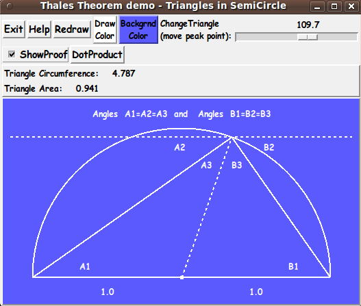
When the 'ShowProof' checkbutton is used to show the proof, a text window pops up (in additon to the drawing of the 'proof lines and angle-labels') --- to explain the proof.
And when the 'DotProduct' button is clicked, a text window pops up showing the dot-product calculations for the CURRENT configuration of the triangle on the canvas.
I have replaced the code above with the new code.
For several months, I have had it on my 'to do' list to add these 'proof items' to this script. Now I am positioned to use the techniques and procs that I developed for this script in making other geometry-proof scripts. I have about 50 such proofs on my 'to do' list. That should keep me busy for the next few years --- along with my 'to do' scripts in many other categories.
Comments Section
Please place any comments here, Thanks.