tkImageGridWarp - GIF/PNG/JPEG/other - using a barymetric technique on triangles
uniquename - 2014mar24
For about a year now (since about early-2013), I have had an 'image-warp-via-grid' item on my 'to-do' list --- which is at the bottom of my 'bio' page at uniquename.
My intent was to use a rectangular grid but to do the 'color mapping' from the original image onto the warped grid via triangles in the rectangles --- by using 'barymetric coordinates'.
Back on 2013sep05, I posted code using a barymetric technique --- at the wiki page
3-Color-Gradient Isosceles Triangle - Barymetric Blend with Shaded Edges
On that color-shaded-isoceles-triangle page, I present a Tk script that peforms a color blend using barymetric coordinates.
I knew that I could use similar mathematics to do the 'grid-warp' of a given image using 'barymetric coordinates' on triangles --- to associate pixels in a 'moved triangle' to pixels in the corresponding, original, not-moved triangle (and the underlying, original image).
See that wiki page above (#38676) for details on the barymetric mathematics involved and for further sources on barymetric coordinates and math.
---
THE GOALS
My main goals for the 'image warp' Tcl-Tk script were:
1) Provide a GUI for selecting an image file (GIF, PNG, JPEG, or about 100 other types).
2) Provide a grid of movable points, for the user to define the warp.
3) Provide the user a way to easily change the grid to have a different number of 'segments' in the x and y directions.
4) Provide a way to easily hide the grid (points and lines), so that the warped image can be captured without the grid showing.
5) Devise the procs in the script in a modular fashion, so that essentially any operation can be done by the user, in almost any order, and reasonable results/responses will be obtained.
(I am currently not concerned with handling transparency in GIF and PNG images. So, in the code below, I have not included code to handle transparency information in either of those 2 types of image file.)
SCREENSHOT OF THE GUI
On the basis of the goals above (and after many days of coding and testing --- and re-designing and re-coding and re-testing --- and almost giving up), I ended up with the GUI seen in the following image.
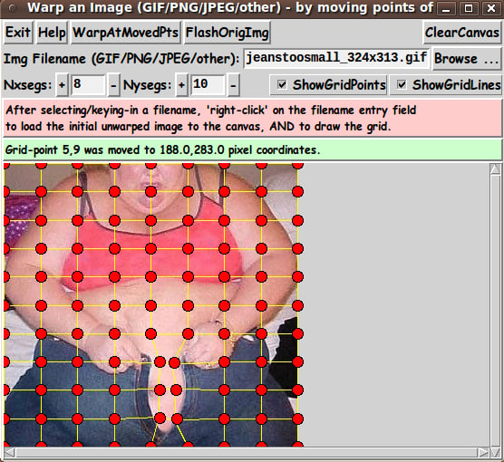
Note that there are two entry fields in which to set the parameters 'Nxsegs' and 'Nysegs' that control the 'fineness' of the grid.
Also note that there are a couple of 'label' widgets across the middle of the GUI --- one label for giving a brief guide on how to load an image to the canvas (with a grid) --- and one 'status' label to allow for communicating to the user how the warp processing is going.
---
TYPICAL SEQUENCE OF OPERATIONS WITH THE GUI
STEP 1:
Select the image file to be warped. This is most conveniently done with the 'Browse...' button on the GUI.
STEP 2:
As indicated in a brief 'guide' on the GUI, the user can 'right-click' (with mouse-button-3) on the filename entry field to cause the image file to be read and its image shown on the 'canvas'.
STEP 3:
The 'fineness' of the grid can be set via 'Nxsegs' and 'Nysegs' entry fields on the GUI --- which specify the number of grid 'segments' in the x and y directions.
The grid consists of (Nxsegs + 1) times (Nysegs + 1) points. For example, if Nxsegs = 20 and Nysegs = 10, there are 21 x 11 = 231 points in the rectangular grid --- and 20 x 10 = 200 rectangles.
(Also 2 * (20 x 10) + 20 + 10 = 430 lines are drawn in the grid.)
You can button1-Press-and-Hold on the '+' and '-' buttons beside the Nxsegs and Nysegs entry fields to change the numbers rather rapidly --- but not so rapidly that they advance more than one unit at a time.
Or you can simply enter numbers in those two fields. Then, like the filename entry field, 'right-click' (mouse-button3-release) or use the Return key to cause the new segments number(s) to be applied. A new grid will be built on the canvas.
STEP 4:
The user moves one or more grid points, by clicking on the canvas near a grid point and dragging the grid-point with mouse-button-1.
When done moving a set of grid points, click on the 'WarpAtMovedPts' button to cause the image to be warped according to all the grid points that were moved.
Repeat these steps as needed.
If things get confusing, the user can click on a 'ClearCanvas' button, then reload the image file to the canvas (with a 'right click' on the filename entry field) and start fresh.
---
When one goes through these steps and gets a warped image, it can be nice to compare the warped image to the original image.
The 'FlashOrigImg' button is meant to accomplish this --- by showing the original image over the warped image for a couple of seconds, and then removing it.
---
USING THE WARPED IMAGE:
To keep the GUI relatively simple, there is no 'SaveAs-GIF/PNG/JPEG' button on the GUI --- as seen in the images above.
A SCREEN/WINDOW CAPTURE UTILITY (like 'gnome-screenshot' on Linux) can be used to capture the GUI image in a PNG file, say.
Note that you can use the 'ShowGridPoints' and 'ShowGridLines' checkbuttons on the GUI to turn off the display of the grid on the image, before doing an image capture.
If necessary, an image editor (like 'mtpaint' on Linux) can be used to crop the window-capture image. The image could also be down-sized --- say, to make a smaller image suitable for a web page or an email. And the image could be converted from PNG to GIF or JPEG --- for example, by using the ImageMagick 'convert' command.
MAKING ANIMATED GIF's:
Note that given a warped image, one could make an animated GIF --- which flashes back and forth between the original image and the warped image.
For example, the 2 images could be combined to make an animated GIF --- using a program like ImageMagick 'convert'. Example command:
convert -delay 100 -loop 0 file1 file2 output_ani.gif
where the delay time of 100 is in 100ths of seconds, giving an inter-image wait time of 1.0 seconds. The parameter '-loop 0' indicates that the animated GIF file should be played indefinitely, rather than stopping after a finite number of cycles.
In fact, that is what I have done with the image seen in the screenshot above.
Here is the original image.

Here is the warped image, that I captured using the technique outlined above --- 'gnome-screenshot' with the 'mtpaint' image editor used to crop the image.

And here is the resulting animated GIF file.

By using this 'tkImageGridWarp' utility, we can help this person button those too-small jeans.
THE CODE
Below, I provide the Tk script code for this 'grid-warp-an-image' utility.
I follow my usual 'canonical' structure for Tk code for this Tk script:
  0) Set general window & widget parms (win-name, win-position,
     win-color-scheme, fonts-for-widgets, widget-geometry-parms,
     text-array-for-labels-etc, win-size-control).

  1a) Define ALL frames (and sub-frames, if any).
  1b) Pack   ALL frames and sub-frames.

  2) Define & pack all widgets in the frames, frame by frame.
              Within each frame, define ALL the widgets.
              Then pack the widgets.

  3) Define keyboard and mouse/touchpad/touch-sensitive-screen action
     BINDINGS, if needed.

  4) Define PROCS, if needed.

  5) Additional GUI initialization (typically with one or more of
     the procs), if needed.
This Tk coding structure is discussed in more detail on the page A Canonical Structure for Tk Code --- and variations.
This structure makes it easy for me to find code sections --- while generating and testing a Tk script, and when looking for code snippets to include in other scripts (code re-use).
I call your attention to step-zero. One thing that I started doing in 2013 is use of a text-array for text in labels, buttons, and other widgets in the GUI. This can make it easier for people to internationalize my scripts. I will be using a text-array like this in most of my scripts in the future.
EXPERIMENTING WITH THE GUI
As in all my scripts that use the 'pack' geometry manager (which is all of my 100-plus scripts, so far), I provide the four main pack parameters --- '-side', '-anchor', '-fill', '-expand' --- on all of the 'pack' commands for the frames and widgets.
That helps me when I am initially testing the behavior of a GUI (the various widgets within it) as I resize the main window.
I think that I have used a pretty nice choice of the 'pack' parameters. The label and button and checkbutton widgets stay fixed in size and relative-location if the window is re-sized --- while the filename entry widget expands/contracts horizontally whenever the window is re-sized horizontally.
And the canvas expands both horizontally and vertically when the window is resized.
For example, if the user clicks on the Maximize button of the window, the window-manager expands the window to screen-size --- and the filename entry field expands to maximum size horizontally, and the canvas expands to maximum size both horizontally and vertically.
You can experiment with the '-side', '-anchor', '-fill', and '-expand' parameters on the 'pack' commands for the various frames and widgets --- to get the widget behavior that you want.
___
Additional experimentation: You might want to change the fonts used for the various GUI widgets. For example, you could change '-weight' from 'bold' to 'normal' --- or '-slant' from 'roman' to 'italic'. OR change font families.
In fact, you may NEED to change the font families, because the families I used may not be available on your computer --- and the default font that the 'wish' interpreter chooses may not be very pleasing.
I use variables to set geometry parameters of widgets --- parameters such as border-widths and padding. And I have included the '-relief' parameter on the definitions of frames and widgets. Feel free to experiment with those 'appearance' parameters as well.
If you find the gray 'palette' of the GUI is not to your liking, you can change the value of the RGB parameter supplied to the 'tk_setPalette' command near the top of the code.
SOME FEATURES IN THE CODE
That said, here's the code --- with plenty of comments to describe what most of the code-sections are doing.
You can look at the top of the PROCS section of the code to see a list of the procs used in this script, along with brief descriptions of how they are called and what they do.
The main procs are
   'get_img_filename'      - called by the 'Browse...' button beside
                             the entry field for the image file.

   'get_chars_before_last' - called by procs 'get_img_filename' and
                             'checkFile_convertToGIF'.

   'checkFile_convertToGIF' - called by proc 'get_img_filename'. This is
                              the proc that accepts a non-GIF file and
                              makes a '.gif' file from it.

   'load_file_to_canvas'   - called by button1-release or <Return> on
                             the filename entry field.

 The following 6 procs are called by 'load_file_to_canvas', to get started.

   'create_photoID0'       - called by procs 'load_file_to_canvas'.

   'create_photoID1'       - called by proc 'load_file_to_canvas'.

   'set_scrollregion_size' - called by proc 'load_file_to_canvas'.

   'put_img1_on_canvas'    - called by procs 'load_file_to_canvas'.

   'initialize_grid_arrays' - called by procs 'load_file_to_canvas'.

   'draw_grid1'            - called by procs 'load_file_to_canvas'.

  Note that if one wants to RESTART with a new image --- by changing the
  image data in the named image file, or by switching to a new image filename
  --- the RESTART can be effected by running the above 6 procs again ---
  by simply calling the 'load_file_to_canvas' proc.

  We should also consider which of the above procs should be rerun
  when the x,y grid-segments entries are changed. Note that changing
  x,y grid-segments requires rerunning the last two procs ---
  'initialize_grid_arrays' and 'draw_grid1'.

 The following 3 procs handle moving a grid-point.

   'move_pointSelect'  - called by a button1-press   binding on a point-tag of the canvas.
   'move_point'        - called by a button1-motion  binding on the canvas.
   'move_pointEnd'     - called by a button1-release binding on a point-tag of the canvas.

   'delete_lines_at_ij'    - called by proc 'move_pointEnd', to delete
                             the 4 lines connected to the moved grid-point.

   'redraw_lines_at_ij'    - called by proc 'move_pointEnd', to redraw
                             the 4 lines connected to the moved grid-point.

 The following 3 procs handle the warping.

 'warp_at_moved-points' - called by 'WarpAtMovedPts' button. Calls the 'warp_inQuad'
                          proc in a loop.

   'warp_inQuad'       - called by the 'warp_at_moved-points' proc.

                         This proc is called in 'warp_at_moved-points' for each
                         'grid1' quadrangle that has been changed.

                         At a changed quadrangle, this 'warp_atQuad' proc
                         makes a new image 'barymetrically' --- using 2 triangles
                         in the indicated quadrangle.

                         See rough diagram of the triangles in comments in this code.

                         For a given one of the triangles,
                         the barymetric warp is done by a 'barymetric mapping' between
                         the 'moved triangle' and the corresponding unwarped triangle
                         on the original stored stored image.

                         The pixels in the 'moved triangle' are 'colored' according
                         to the corresponding pixels in the unwarped triangle on the
                         original image.

  'fill_grid1_triangle_with_corners'  - called by the 'warp_inQuad' proc,
                                        to handle the barymetric color-mapping
                                        for each triangle. This is where the
                                        barymetric math resides.

  This proc lets the user see the original image:

   'flash_orig_img'         - called by the 'FlashOrigImg' button.

 The following 4 procs handle the '+' and '-' buttons beside the
 Nxsegs and Nysegs entry fields.

   'incr_nxsegs'       - called by button1-press binding on Nxsegs '+' button
   'decr_nxsegs'       - called by button1-press binding on Nxsegs '-' button
   'incr_nysegs'       - called by button1-press binding on Nysegs '+' button
   'decr_nysegs'       - called by button1-press binding on Nysegs '-' button

   'reload_grid'  - called by button3-release or Return bindings on the
                    Nxsegs and Nysegs entry fields.

 The following 2 procs handle the Show Points/Lines checkbuttons.

 'hide-show_grid_points' - called by button1-release binding on the points checkbutton
 'hide-show_grid_lines'  - called by button1-release binding on the lines checkbutton


   'popup_msgVarWithScroll' - used to show messages to the user, as well as
                              the HELPtext for this utility via the 'Help' button.
---
Modularity of procs
One of the trickiest things about this GUI involved finding a way to break up the necessary operations into a 'modular' form in the procs --- so that the groups-of-operations would support the various user-actions that might be needed via the GUI widgets.
Comments at the top of the code indicate how I outlined the sequence of operations to be implemented and how I grouped those operations into separate procs.
Even if it is necessary to change, somewhat, the way the operation-groups are performed via 'events' on the widgets of the GUI, the 'granularity' of the modular break-down of the operations into procs will probably serve to facilitate a relatively easy change to accomodate the necessary operations triggered by any particular widget-event.
---
JPEG and PNG (and other non-GIF image formats)
Another challenge was to be able to handle JPEG and PNG files as well as GIF files --- without requiring the user to install a '3rd party' Tk-extension to handle reading JPEG files --- or to install Tk 8.6 to handle reading PNG files.
I settled on using the 'exec' command to issue the ImageMagick 'convert' command.
Code fragment in proc 'checkFile_convertToGIF':
set RETcode [catch {exec convert "$INfilename" -colors 256 "$tempFilename"} CatchMsg]where 'tempFilename' contains a name that ends with '.gif'.
In fact, the proc 'checkFile_convertToGIF' includes an 'exec' of the 'file' command to determine if the $INfilename file is a GIF file --- via use of the Tcl 'string match' command.
If the file is determined to be a GIF file, then 'convert' is not used. But, for any other file, the file is converted to a GIF file.
So this utility will actually warp any of the 100-plus types of image file supported by the ImageMagick 'convert' command --- by converting such files to a new '.gif' file. Reference: http://www.imagemagick.org/script/formats.php
So this utility will convert PGM (Portable Gray Map), PPM (Portable Pixel Map), TIFF (Tagged Image File Format), TGA (Targa), XWD (X Window Dump) and other types of image files to '.gif' files --- and do the warp with those GIF files.
---
"Flashing" the original image
Implementation of the 'flash-the-original-image' option (when the user clicks on the 'FlashOrigImg' button) was done by the following statements in proc 'flash_orig_img':
   .fRcanvas.can create image 0 0 -anchor nw \
      -image $IDimg0 -tag TAGimg0

   update

   after 2000

   .fRcanvas.can delete TAGimg0
---
Handling huge images
To be able to scroll huge images, a '-scrollregion' parameter is used to configure the (scrollable) canvas --- in proc 'set_scrollregion_size'.
There are probably other noteworthy 'features' of the code that could and should be mentioned here.
In fact, it would probably be helpful to provide some 'lessons learned' about
** the 'move_point' procs and their bindings to tag or canvas
** the need to keep the grid-points 'above' the grid-lines, so that the grid-lines do not interfere with selecting a grid-point to move.
There are a few comments in the code on these issues, but they deserve a little more discussion. However, this 'features of the code' section is long enough as is. Enough for now.
It is my hope that the copious comments in the code will help Tcl-Tk coding 'newbies' get started in making GUI's like this.
Without the comments, potential young Tcler's might be tempted to return to their iPhones and iPads and iPods --- to watch videos of Steven Colbert imitating his hero --- Bill O'Reilly.
Code for Tk script 'tkImageGridWarp_withFixedEdge.tk' :
#!/usr/bin/wish -f
##
## SCRIPT: tkImageGridWarp_withFixedEdge.tk
##
## PURPOSE: This Tk GUI script allows the user to select an image file
## (GIF or PNG or JPEG or other). The file is read and the image
## data that it contains is displayed on a canvas on which a grid
## of points-and/or-lines can be displayed.
##
## The grid precisely covers the rectangular image on the canvas.
##
## The INTERIOR grid-points are movable. And ... the grid points
## on the outer edge of the image are NOT moveable.
##
## (A future enhancement could allow for 'SLIDING' the 'edge' grid points
## along the edges of the image --- or even pulling them 'INWARD'.
## However, the grid-handling code becomes quite a bit more complex.
## So it might be good to keep this script intact and make a new
## 'tkImageGridWarp_withSemiFixedEdge.tk' script.
## An even more enhanced script would allow for a margin around
## the image and allow for pushing the 'edge' grid points 'OUTWARD'.)
##
## The user moves one or more INTERIOR grid points to cause the
## image to be warped. When done moving a set of grid points, the user
## can click on a 'WarpAtMovedPts' button to cause the image to be
## warped according to ALL the grid points moved.
##
## The user can specify, via widgets on the GUI, the number of
## horizontal and vertical 'segments' in the grid --- say
## 'Nxsegs' and 'Nysegs'.
##
## Thus the user can change the grid and then move points of the
## new grid and click on 'WarpAtMovedPts' to perform a new warp.
##
## The user can hide the grid points and/or lines --- typically
## to prepare for taking a 'snapshot' of the warped image.
##
## If things get confusing, the user can click on a 'ClearCanvas'
## button, then reload the image file to the canvas and start fresh.
##
## A 'FlashOrigImg' button allows for 'flashing' the original image
## on top of the warped image --- to quickly compare the current
## warp to the original image.
##
## In case the warp processing drags on for a while, some status
## messages are posted in a status line on the GUI, to indicate
## which grid point is currently being processed.
##
##+#########################
## PLANNED LAYOUT OF THE GUI:
##
## ------------------------------------------------------------------
## Warp an Image - by moving interior points of a grid
## [window title]
## ------------------------------------------------------------------
##
## {Exit} {Help} {WarpAtMovedPts} {FlashOrigImg} {ClearCanvas}
## [A background-color button could be implemented.]
##
## Img1 Filename (GIF/PNG/JPEG/...): ___________________________________ {Browse...}
##
## Nxsegs: {+}___{-} Nysegs: {+}____{-} X ShowGridPoints X ShowGridLines
##
## After selecting/keying-in filename, 'right-click' on the filename entry field to
## load the image to the canvas AND draw the grid.
## [This guide is in a label widget.]
##
## Warp-processing status messages appear here.
## [This status-line is in a label widget.]
##
## ---------------------------------------------------------------------------------
## | A
## | |
## | |
## | Canvas for displaying the initial image, |
## | the grid, and the warped image. |
## | |
## | 'Flashing' the original image is also done here. |
## | |
## | |
## | V
## <------------------------------------------------------------------------------->
##
## SKETCH CONVENTIONS for this GUI sketch:
##
## SQUARE-BRACKETS indicate a comment (not to be placed on the GUI).
## BRACES indicate a Tk 'button' widget.
## A COLON indicates that the text before the colon is on a 'label' widget.
## UNDERSCORES indicate a Tk 'entry' widget.
## CAPITAL-X indicates a Tk 'checkbutton' widget.
## CAPITAL-O indicates a Tk 'radiobutton' widget (if any).
##
## A LINE (HYPHENS or VERTICAL-BARS) WITH AN 'ARROW-HEAD' AT EACH END indicates a Tk 'scale' widget.
##
## A combination of VERTICAL-BAR CHARACTERS AND HYPHEN (or UNDERSCORE) CHARACTERS,
## that outline a RECTANGULAR SHAPE, are used to indicate either a Tk 'listbox' or
## a Tk 'canvas' widget or a Tk 'text' widget.
##
## SCROLL-BAR 'ARROW-HEADS' (for a 'listbox', 'canvas', or 'text' Tk widget)
## are drawn as follows:
##
## UP ARROW-HEAD is drawn with a CAPITAL-A.
## DOWN ARROW-HEAD is drawn with a CAPITAL-V.
## LEFT ARROW-HEAD is drawn with a LESS-THAN sign.
## RIGHT ARROW-HEAD is drawn with a GREATER-THAN sign.
##
##
## UP-and-DOWN ARROW-HEADS at the right/left of the box shape indicate a VERTICAL SCROLL-BAR there.
##
## LEFT-and-RIGHT ARROW-HEADS at the bottom/top of the box shape indicate a HORIZONTAL SCROLL-BAR there.
##
## The arrow-heads on a horizontal scrollbar are joined by hyphens, rather than underscores.
##
##+##################
## GUI WIDGET SUMMARY:
##
## This GUI will contain about:
##
## 10 'button' widgets
## 5 'label' widgets (or more)
## 3 'entry' widgets
## 0 'scale' widgets
## 2 'checkbutton' widgets
## 0 'radiobutton' widgets
## 1 'canvas' widget (with x-y scrollbars)
## 0 'listbox' widgets
## 0 'text' widgets
##
##+#########################################################
## MATHEMATICAL ('BARYMETRIC') METHOD USED to warp the image:
##
## Warping is done, in this script, via barymetric coordinates in
## TRIangles within 4 rectangles/quadrangles around each INTERIOR
## grid point of a 'warpable grid'.
##
## So that we use the same triangle configuration around each
## grid point, we adopt the following configuration of triangles
## in the 4 rectangles/quadrangles around each INTERIOR grid point.
##
## (+ denotes a grid point)
##
## M-1,N-1 M,N-1 M+1,N-1
## +-------+-------+
## | /| /|
## | / | / |
## | / | / |
## |/ M,N|/ |
## M-1,N +-------+-------+ M+1,N
## | / | /|
## | / | / |
## | / | / |
## |/ |/ |
## +-------+-------+
## M-1,N+1 M,N+1 M+1,N+1
##
## (We arbitrarily choose to make the diagnals go upward
## to the northeast, rather than to the northwest.
##
## This triangulation gives a certain 'bias' to the warping
## process, but most visual 'bias-effects' can be minimized
## by the user choosing a fine-enough grid.
##
## The advantage to this consistent triangulation pattern
## around each interior grid point is that the program logic
## becomes less complex than with a 'fancier' triangulation.)
##
## When an INTERIOR grid point M,N is moved, 6 of these
## 8 triangles are moved. (By 'moved', we mean that the xy
## coordinates of at least one of the 3 vertices in a
## moved-triangle changed.)
##
## Only the upper-left and the lower-right triangles are
## left unmoved. Their 3 vertices do not move when M,N moves.
##
## If the point M,N is moved, the shape of 6 triangles changes
## --- in the 4 rectangles/quadrangles surrounding grid-point M,N.
##
## We will assign 'i,j' ID's to the rectangles/quadrangles, like we have
## to the grid-points. We choose to use the 'i,j' ID of the lower-right
## grid-point of a quadrangle to be the ID of the quadrangle.
##
## So, in the diagram above:
## - the upper-left quadrangle has ID 'M,N'
## - the upper-right quadrangle has ID 'M+1,N'
## - the lower-left quadrangle has ID 'M,N+1'
## - the lower-right quadrangle has ID 'M+1,N+1'
##
## If the ID's of the grid-points go from
## 0 to Nxsegs and 0 to Nysegs,
## then the ID's of the quadrangles go from
## 1 to Nxsegs and 1 to Nysegs.
##
## Note that if grid-point M,N is moved, then we have to
## consider doing warping-processing in the 4 quadrangles
## around M,N --- the quadrangles with QUADRANGLE-ID's:
## 'M,N' 'M+1,N' 'M,N+1' 'M+1,N+1'
##
## And we have to do warping processing on at least 6 of the
## 8 triangles in those 4 quadrangles.
##
## If only grid-point M,N were moved and none of its neighboring grid
## points are moved (in particular, M-1,N-1 and M+1,N+1 are not moved),
## then 2 of the triangles in the 4 quadrangles around point M,N
## do not move, and no warping processing would have to be done on
## those 2 triangles. BUT ...
##
## Note that since other grid-points around M,N will (in general)
## be moved --- even those other 2 triangles may have been
## moved and will (in general) have to be processed.
##
##+######################################
## ARRAYS FOR THE GRID POINT COORDINATES: ('grid1' and 'grid0')
##
## In this code,
## the current location (in pixels, on the scrollable canvas) of the
## grid points is stored in a pair of arrays with indices of the form
## "$i,$j" --- aRgrid1Xpx($i,$j) and aRgrid1Ypx($i,$j) --- where
## i goes from 0 to Nxsegs and j goes from 0 to Nysegs.
##
## (We use a PAIR of X,Y arrays with a SINGLE numeric value
## for each index "$i,$j" --- rather than a SINGLE array
## with a PAIR of numeric values for each index. This allows
## us to avoid repeatedly using the 'foreach-break' technique
## that is typically used in Tcl-Tk code to extract individual
## numbers from a 'tuple' of numbers.)
##
## In order to perform the warp from the original image, we use
## an additional pair of arrays --- aRgrid0Xpx($i,$j) & aRgrid0Ypx($i,$j)
## --- to store the coordinates of the 'original', undistorted grid.
##
##+#####################################################
## ARRAY TO KEEP TRACK OF CHANGED-RECTANGLES/QUADRANGLES: (of 'grid1')
##
## When the user moves a set of grid-points and then clicks on the
## 'WarpAtMovedPoints' button to do the warp, this code should 'sweep'
## over the grid and peform the warp-processing (coloring pixels in
## 'moved triangles' according to pixel-colors in the corresponding
## 'unwarped triangle' on the original unwarped image) ---
## performing the processing just once for each triangle moved.
##
## One way of doing this is to use an array to keep track of which
## RECTangles/QUADrangles have been affected by a grid-point move.
## Then we can sweep over the rectangles/quadrangles, that is, over
## the QUADRANGLE-ID's (1 to Nxsegs, 1 to Nysegs) and do the
## warp-processing (a color mapping of between a warped triangle
## and the original unwarped triangle) for each of the 2 triangles
## in a 'marked' rectangle/quadrangle.
##
## When the user moves a grid-point --- M,N say --- this code will use
## an array 'aRquad1warped0or1(i,j)', where i is between 1 and Nxsegs
## and j is between 1 and Nysegs, to keep track of which
## rectangles/quadrangles have been warped and will need warp-processing.
##
## When an INTERIOR grid point is moved, 4 rectangles/quadrangles
## will be marked for processing, by setting 4 'i,j' elements of
## array 'aRquad1warped0or1' to 1 --- for the 4 rectangles/quadrangles
## affected.
##
## When the user clicks on the 'WarpAtMovedPoints' button, the code
## will sweep over the indices 1 to Nxsegs and 1 to Nysegs, and for
## the 'marked' rectangles/quadrangles, the code will perform the
## warp-processing for the pair of triangles in each 'marked'
## rectangle/quadrangle.
##
##+#########################################################
## THE TYPICAL SEQUENCE OF USER-STEPS (and procs) IN WARPING:
##
## 0) The user selects a file via the 'Browse...' button, to put
## the selected filename in the filename entry widget.
##
## IMPLEMENTATION IS VIA PROC: 'get_img_filename'
##
## 1) When the user 'right-clicks' on the filename entry field
## (or uses the Return key), the following sequence of operations
## is performed.
##
## 1a) PROC 'create_photoID0':
## The Tk 'image create photo' command is used to create a Tk
## 'photo' image structure (and its identifier, 'IDimg0' say)
## --- to hold the pixel data of the original, undistorted image.
##
## 1b) PROC 'create_photoID1':
## The Tk 'image create photo' command is used to create a Tk
## 'photo' image structure (and its identifier, 'IDimg1' say)
## --- to hold the pixel data of the warpable image. It is 'IDimg1'
## that we (later) put on the 'scrollable' canvas.
##
## 1c) PROC 'set_scrollregion_size':
## The 'IDimg0' image size is used to set a 'scrollregion' size
## for the scrollable canvas. This allows for handling very
## large images.
##
## 1d) PROC 'put_img1_on_canvas':
## The 'warpable'-image, IDimg1, is put on the canvas with
## a canvas 'create image' command.
## (NOTE: From this point on, warping operations are to
## be done on the IDimg1 in-memory 'structure', NOT
## on the IDimg0 in-memory 'structure'.)
##
## 1e) PROC 'initialize_grid_arrays':
## The arrays 'aRgrid0Xpx' & 'aRgrid0Ypx'
## AND 'aRgrid1Xpx' & 'aRgrid1Ypx' are initialized with
## grid-point pixel coordinates according to the 'IDimg0'/'IDimg1'
## image size and the value of 'Nxsegs' and 'Nysegs'.
##
## 1f) PROC 'draw_grid1':
## If the 'ShowGridPoints' checkbutton is ON (initially it is),
## grid POINTS are drawn on the image, according to the contents
## of aRgrid1, the warpable grid.
## If the 'ShowGridLines' checkbutton is ON (initially it is),
## grid LINES are drawn on the image, according to the contents
## of aRgrid1, the warpable grid.
##
## NOTE: The 'initialize_grid_arrays' and 'draw_grid1' procs
## can be used to reset the grid arrays and redraw the
## grid if the user changes Nxsegs or Nysegs.
##
## IN SUMMARY, for a 'right-click' event on the filename entry
## field, IMPLEMENTATION is done VIA:
## - proc 'create_photoID0'
## - proc 'create_photoID1'
## - proc 'set_scrollregion_size'
## - proc 'put_img1_on_canvas'
## - proc 'initialize_grid_arrays'
## - proc 'draw_grid1'
## which are grouped together in proc 'load_file_to_canvas'.
##
## 2) If the user moves (drags) a grid point:
##
## 2a) The index "$i,$j" of a grid-point to be moved is determined at
## a button1-PRESS event. Only an INTERIOR grid-point is allowed
## to be selected. (Reference: proc 'move_pointSelect')
##
## Button1-MOTION events determine the 'delta' x,y distances
## that the selected grid point should be moved. (Reference:
## proc 'move_point')
##
## At button1-RELEASE, the new location is stored in array
## elements aRgrid1Xpx($i,$j) and aRgrid1Ypx($i,$j). (Reference:
## proc 'move_pointEnd')
##
## These three button1 events --- PRESS, MOTION, RELEASE --- are
## bound to the 3 'move_point' procs. See the BINDINGS section for details.
##
## 2b) After the user has moved one or more grid points, the 'grid-warp' is
## initiated by clicking on the 'WarpAtMovedPts' button, which calls
## the 'warp_at_moved-points' proc.
##
## The 'warp_at_moved-points' proc does its job by calling the proc
## 'warp_inQuad $i $j' in a loop over i,j --- for those
## rectangles/quadrangles that have been affected by grid-point moves
## on 'grid1'.
##
## (The rectangles/quadrangles of grid1 that have been affected are indicated
## by a 1, rather than 0, in the array 'aRquad1warped0or1' which is
## indexed by indices i,j going from 1,1 to Nxsegs,Nysegs.)
##
## The 'warp' at each of the 2 triangles in each 'marked' quadrangle
## is done by a 'barymetric mapping' from the 'grid1 triangle'
## to the corresponding, original 'grid0' triangle.
##
## The colors of pixels in IDimg1 (the warped image) are set according to
## the color of corresponding pixels in IDimg0 (the original unwarped image).
##
## Any given triangle is processed by proc 'fill_grid1_triangle_with_corners'.
## That is the proc that contains all the 'barymetric' mathematics.
##
## In summary, step2, 'drag-and-warp' IMPLEMENTATION, is done VIA:
## - 3 'move_point' procs
## and
## - a 'warp_at_moved-points' proc which calls proc 'warp_inQuad $i $j',
## which calls 'fill_grid1_triangle_with_corners' --- 2 times for
## each 'marked' quadrangle.
##
##+######################
## NOTE ON THE MANY PROCS:
##
## It is hoped that the 'modular' breakdown of the needed-computing
## into the many procs outlined above will (eventually) serve in
## implementing various 'change' operations --- such as hide/show grid,
## change number of grid rows/columns, change image --- without
## repeating a lot of code.
##
##+###################################
## NOTES ON GIF versus PNG versus JPEG (and other image formats):
## (as things stand with Tk in 2014 March)
##
## 1) For the 'wish' interpreter of Tk 8.6, 8.5, and older:
## 'image create photo' does not support reading JPEG-JFIF image files.
## To do this with (what looks like) Tcl-Tk commands, one must
## resort to a Tk 'extension'.
##
## 2) Tk 'image create photo' command did not support reading PNG files until
## late 2013 --- when version Tk 8.6 of the 'wish' interpreter was released.
## That is, version 8.5 and older of the 'wish' interpreter does not support
## the use of PNG files.
##
## Rather than require a user to install a Tk extension and/or upgrade
## their version of Tcl-Tk to 8.6, this utility assumes that
## the ImageMagick (IM) 'convert' command is available to the user.
##
## The 'get_img_filename' proc uses IM 'convert' to convert JPEG and PNG
## files (and about 100 other types of image files) to GIF files.
##
## It is the GIF file that is used by 'image create photo' commands to load
## IDimg0 (the original, unwarped imaged) and IDimg1 (the image to-be-warped).
##
## ---
##
## NOTE: The conversion to GIF can result in a loss of image quality ---
## especially when there are (many) more than 256 color shades in the
## JPEG or PNG file. A common effect in these cases is 'color banding'
## in the converted image.
##
## For example, 'computer desktop wallpaper' images, which often consist
## of gradual gradiations of colors across the large image, are subject
## to 'color banding' when converted to GIF files.
##
## Furthermore, landscape and other nature photographs (usually in JPEG
## format) typically consist of many more than 256 colors and result in
## rather 'grainy'/'aliased' images when they are converted to GIF files.
##
## When a version of the Tk 'wish' interpreter is available that 'natively'
## supports both JPEG-JFIF-read and PNG-read, then this utility could
## easily be changed to eliminate the use of the 'convert' program ---
## in the 'get_img_filename' proc --- which calls a 'checkFile_convertToGIF'
## proc to make a '.gif' from non-GIF image files.
##
## By the way, if a new '.gif' file is made, it is put in the directory
## with the non-GIF image file.
##
##+#######################
## BARYMETRIC INFO SOURCES:
##
## This Tk script peforms the warp using 'barymetric coordinates'
## on triangles --- to associate pixels in a warped triangle to
## pixels in the corresponding, original, un-warped triangle
## (and the underlying, original image).
##
## I have based the Tcl code for the barymetric mathematics on the code that
## I posted on 2013sep05 at https://wiki.tcl-lang.org/38676 in a web page titled
## '3-Color-Gradient Isosceles Triangle - Barymetric Blend with Shaded Edges'.
##
## See that web page for details and further sources.
##
##+################################
## USING THE GENERATED WARPED IMAGE:
##
## A screen/window capture utility (like 'gnome-screenshot'
## on Linux) can be used to capture the GUI image in a PNG
## or GIF file, say.
##
## If necessary, an image editor (like 'mtpaint' on Linux)
## can be used to crop the window capture image. The image
## could also be down-sized --- say to make a smaller image
## suitable for a web page or an email.
##
## The captured-image file could be used with a utility (like the
## ImageMagick 'convert' command) to change a color of the image
## to TRANSPARENT, making a transparent GIF (or PNG) file --- OR
## to make a sequence of transparent GIF's for making a transparent
## ANIMATED GIF file.
##
##+########################################################################
## 'CANONICAL' STRUCTURE OF THIS TK CODE:
##
## 0) Set general window & widget parms (win-name, win-position,
## win-color-scheme, fonts, widget-geometry-parms,
## text-array-for-labels-etc, win-size-control).
##
## 1a) Define ALL frames (and sub-frames, if any).
## 1b) Pack ALL frames and sub-frames (that are to show initially).
##
## 2) Define all widgets in the frames, frame-by-frame.
## When ALL the widgets for a frame are defined,
## pack ALL the widgets in the frame.
##
## 3) Define keyboard and mouse/touchpad/touch-sensitive-screen 'event'
## BINDINGS, if needed.
##
## 4) Define PROCS, if needed.
##
## 5) Additional GUI INITIALIZATION (typically with one or two of the procs),
## if needed/wanted.
##
##+####################################
## MORE DETAIL ABOUT THE CODE STRUCTURE of this particular script:
##
## 1a) Define ALL frames:
##
## Top-level : '.fRbuttons'
## '.fRfile'
## '.fRgrid'
## '.fRguide'
## '.fRstatus'
## '.fRcanvas'
##
## Sub-frames: none for any of these frames
##
## 1b) Pack ALL the frames --- top to bottom.
##
## 2) Define all widgets in the frames (and pack them):
##
## - In '.fRbuttons': BUTTON widgets (Exit,Help,WarpAtMovedPts,
## FlashOrigImg,ClearCanvas)
##
## - In '.fRfile': LABEL, ENTRY, and 'Browse...'-BUTTON widgets
##
## - In '.fRgrid': 2 pairs of LABEL, ENTRY, and BUTTON widgets
## and 2 CHECKBUTTON widgets.
##
## - In '.fRguide': one LABEL widget
##
## - In '.fRstatus': one LABEL widget
##
## - In '.fRcanvas': one (scrollable) CANVAS widget
##
## 3) Define BINDINGS:
## - button3-release and <Return> bindings on the filename entry field
## - button1-press and button1-release bindings on point-tags of the canvas
## - button1-motion binding on the canvas
## - button1-release bindings on the {+} and {-} buttons on the GUI
## - button1-release bindings on the Show Points/Lines checkbuttons
##
## See the BINDINGS section in the code below for more info.
##
## 4) Define PROCS:
##
## Some of the main procs follow. See the PROCS section for more details
## --- in the comments and code in the procs, if necessary.
##
## 'get_img_filename' - called by the 'Browse...' button beside
## the entry field for the image file.
##
## 'get_chars_before_last' - called by procs 'get_img_filename' and
## 'checkFile_convertToGIF'.
##
## 'checkFile_convertToGIF' - called by proc 'get_img_filename'.
##
## 'load_file_to_canvas' - called by button1-release or <Return> on
## the filename entry field.
##
## The following 6 procs are called by 'load_file_to_canvas', to get started.
##
## 'create_photoID0' - called by the 'load_file_to_canvas' proc.
##
## 'create_photoID1' - called by the 'load_file_to_canvas' proc.
##
## 'set_scrollregion_size' - called by the 'load_file_to_canvas' proc.
##
## 'put_img1_on_canvas' - called by the 'load_file_to_canvas' proc.
##
## 'initialize_grid_arrays' - called by the 'load_file_to_canvas' proc.
##
## 'draw_grid1' - called by the 'load_file_to_canvas' proc.
##
## The following 3 procs handle grid-point moves.
##
## 'move_pointSelect' - called by a button1-press binding on the points-tag.
## 'move_point' - called by a button1-motion binding on the canvas.
## 'move_pointEnd' - called by a button1-release binding on the points-tag.
##
## The following 3 procs handle the warping at 'moved' grid-points.
##
## 'warp_at_moved-points' - called by 'WarpAtMovedPts' button. Calls the 'warp_inQuad'
## proc in a loop over the changed-only quadrangles.
##
## 'warp_inQuad' - called by the 'warp_at_moved-points' proc.
##
## 'fill_grid1_triangle_with_corners' - called by the 'warp_inQuad' proc.
##
##
## 'flash_orig_img' - called by the 'FlashOrigImg' button.
##
## The following 4 procs handle the '+' and '-' buttons beside the
## Nxsegs and Nysegs entry fields.
##
## 'incr_nxsegs' - called by button1-release binding on Nxsegs '+' button
## 'decr_nxsegs' - called by button1-release binding on Nxsegs '-' button
## 'incr_nysegs' - called by button1-release binding on Nysegs '+' button
## 'decr_nysegs' - called by button1-release binding on Nysegs '-' button
##
## The following 2 procs handle button1-release on the Show Points/Lines checkbuttons.
##
## 'hide-show_grid_points' - called by button1-release binding on the points checkbutton
## 'hide-show_grid_lines' - called by button1-release binding on the lines checkbutton
##
## 'set_background_color' - called by the 'BackgroundColor' button
## (NOT USED. Could be implemented someday, esp. if
## 'edge' grid points were allowed to be pulled inward.)
##
## 'popup_msgVarWithScroll' - used to show messages to the user, such as
## the HELPtext for this utility via the 'Help' button
##
## 5) Additional-GUI-initialization: See that section at the bottom of this script.
##
##+########################################################################
## DEVELOPED WITH:
## Tcl-Tk 8.5 on Ubuntu 9.10 (2009-october release, 'Karmic Koala').
##
## $ wish
## % puts "$tcl_version $tk_version"
## showed 8.5 8.5 on Ubuntu 9.10
## after Tcl-Tk 8.4 was replaced by 8.5 --- to get anti-aliased fonts.
##+#######################################################################
## MAINTENANCE HISTORY:
## Created by: Blaise Montandon 2014mar16 Started coding --- comments, GUI
## widget definitions, some BINDINGS,
## and most of the PROCS, but with
## most of the proc code dummied out.
## Started with the comments and code
## of my 'merge2images.tk' script.
## Created by: Blaise Montandon 2014mar17 Fixed the code to the point that
## the GUI could be started up.
## Changed by: Blaise Montandon 2014mar19 Started coding the procs to put an
## image-file image on the canvas
## with a 'scrollregion' to allow for
## large images.
## Changed by: Blaise Montandon 2014mar20 Started coding the grid-point
## select-and-move procs and 'warp' procs.
## Changed by: Blaise Montandon 2014mar21 Added 'delete_lines_at_ij' and
## 'redraw_lines_at_ij' procs. Added
## 'aRi4pointID' & 'aRj4pointID' arrays
## for 'reverse lookup' of a grid-point
## index "$i,$j" from its Tk canvas
## object (point) ID.
## Changed by: Blaise Montandon 2014mar22 Added the 'FlashOrigImg' button.
## Added the '.fRstatus' frame and several
## status messages in array aRtext'. Added
## 'configure -text' statements in several
## 'warp_' and 'move_point' procs to show
## the status messages.
## Added 'hide-show_grid_points' and
## 'hide-show_grid_lines' procs.
## Updated comments and the HELPtext var.
## Changed by: Blaise Montandon 2014mar25 Changed the 3 warping procs to
## properly handle warped triangles.
## Changed the comments above that
## document the warping process
## and the arrays and procs used.
## In particular, the grid diagram of
## points/quads/triangles was changed.
##+#######################################################################
##+#######################################################################
## Set WINDOW TITLES.
##+#######################################################################
wm title . \
"Warp an Image (GIF/PNG/JPEG/other) - by moving grid points"
wm iconname . "WarpImg"
##+#######################################################################
## Set WINDOW POSITION.
##+#######################################################################
wm geometry . +15+30
##+######################################################
## Set the COLOR SCHEME for the window ---
## and background colors for some of its widgets.
##+######################################################
## For grayish palette.
if {1} {
set Rpal255 210
set Gpal255 210
set Bpal255 210
}
## For bluish palette.
if {0} {
set Rpal255 200
set Gpal255 200
set Bpal255 255
}
set hexPALcolor [format "#%02X%02X%02X" $Rpal255 $Gpal255 $Bpal255]
tk_setPalette "$hexPALcolor"
##+#####################################
## Set color background for some widgets.
##+#####################################
set entryBKGD "#f0f0f0"
set chkbuttBKGD "#c0c0c0"
set textBKGD "#f0f0f0"
# set radbuttBKGD "#c0c0c0"
# set scaleBKGD "#f0f0f0"
# set listboxBKGD "#f0f0f0"
##+################################################
## Initialize the background color for the canvas.
##+################################################
## For black canvas background:
if {1} {
set COLORBKGDr 0
set COLORBKGDg 0
set COLORBKGDb 0
}
## For white canvas background:
if {0} {
set COLORBKGDr 255
set COLORBKGDg 255
set COLORBKGDb 255
}
set COLORBKGDhex \
[format "#%02X%02X%02X" $COLORBKGDr $COLORBKGDg $COLORBKGDb]
##+##########################################################
## Set (temporary) FONT-NAMES.
##
## We use a VARIABLE-WIDTH FONT for LABEL and BUTTON widgets
## --- and the numeric values shown by SCALE widgets.
##
## We use a FIXED-WIDTH FONT for TEXT widgets (to preserve
## alignment of columns in text), LISTBOX widgets (to preserve
## alignment of characters in lists), and ENTRY fields
## (to make it easy to position the text cursor at narrow
## characters like i, j, l, and the number 1).
##+##########################################################
font create fontTEMP_varwidth \
-family {comic sans ms} \
-size -14 \
-weight bold \
-slant roman
font create fontTEMP_SMALL_varwidth \
-family {comic sans ms} \
-size -12 \
-weight bold \
-slant roman
## Some other possible (similar) variable width fonts:
## Arial
## Bitstream Vera Sans
## DejaVu Sans
## Droid Sans
## FreeSans
## Liberation Sans
## Nimbus Sans L
## Trebuchet MS
## Verdana
font create fontTEMP_fixedwidth \
-family {liberation mono} \
-size -14 \
-weight bold \
-slant roman
font create fontTEMP_SMALL_fixedwidth \
-family {liberation mono} \
-size -12 \
-weight bold \
-slant roman
## Some other possible fixed width fonts (esp. on Linux):
## Andale Mono
## Bitstream Vera Sans Mono
## Courier 10 Pitch
## DejaVu Sans Mono
## Droid Sans Mono
## FreeMono
## Nimbus Mono L
## TlwgMono
##+###########################################################
## Set GEOMETRY PARAMETERS for the various widget definitions.
## (e.g. padding & borderwidths & relief for Buttons and Labels)
##
## Relief must be flat, groove, raised, ridge, solid, or sunken.
##+###########################################################
## BUTTON geom parameters:
set PADXpx_button 0
set PADYpx_button 0
set BDwidthPx_button 2
## We generally default to relief "raised" for all 'button' widgets.
## BUT, in case you want to experiment:
set RELIEF_button "raised"
## LABEL geom parameters:
set PADXpx_label 0
set PADYpx_label 0
# set BDwidthPx_label 0
set BDwidthPx_label 2
set RELIEF_label_lo "flat"
## ENTRY geom parameters:
set BDwidthPx_entry 2
## We default to relief "sunken" for all 'entry' widgets.
set initImgfileEntryWidthChars 25
## CHECKBUTTON geom parameters:
set PADXpx_chkbutt 0
set PADYpx_chkbutt 0
set BDwidthPx_chkbutt 1
set RELIEF_chkbutt_hi "raised"
## RADIOBUTTON geom parameters:
# set PADXpx_radbutt 0
# set PADYpx_radbutt 0
# set BDwidthPx_radbutt 1
# set RELIEF_radbutt_hi "raised"
## SCALE geom parameters:
# set BDwidthPx_scale 2
# set initScaleLengthPx 300
# set scaleThickPx 10
## For (small) TEXT widgets:
set BDwidthPx_text 2
# set RELIEF_numtext "sunken"
set RELIEF_numtext "ridge"
# set RELIEF_numtext "groove"
## CANVAS geom parms:
set initCanWidthPx 400
set initCanHeightPx 300
# set BDwidthPx_canvas 2
set BDwidthPx_canvas 0
set RELIEF_canvas "flat"
##+####################################################################
## Set a TEXT-ARRAY to hold text for buttons & labels on the GUI.
## NOTE: This can aid INTERNATIONALIZATION. This array can
## be set according to a nation/region parameter.
##+####################################################################
## if { "$VARlocale" == "en"}
## For the '.fRbuttons' frame:
set aRtext(buttonEXIT) "Exit"
set aRtext(buttonHELP) "Help"
# set aRtext(buttonCOLORBKGD) "Background
# Color"
set aRtext(buttonWARP) "WarpAtMovedPts"
set aRtext(buttonSHOWorig) "FlashOrigImg"
set aRtext(buttonCLEAR) "ClearCanvas"
## For the '.fRfile' frame:
set aRtext(labelFILE) "Img Filename (GIF/PNG/JPEG/other):"
# set aRtext(labelFILE) "Image Filename:"
set aRtext(buttonBROWSE) "Browse ..."
## For the '.fRgrid' frame:
set aRtext(labelNXSEGS) "Nxsegs:"
set aRtext(labelNYSEGS) "Nysegs:"
set aRtext(buttonPLUS) "+"
set aRtext(buttonMINUS) "-"
set aRtext(chkbuttGRIDPOINTS) "ShowGridPoints"
set aRtext(chkbuttGRIDLINES) "ShowGridLines"
## For the '.fRguide' frame:
set aRtext(labelGUIDE) \
"After selecting/keying-in a filename, 'right-click' on the filename entry field
to load the initial unwarped image to the canvas, AND to draw the grid."
## For the '.fRstatus' frame:
set aRtext(labelSTATUS) "Warp-processing status messages appear here."
set aRtext(STATUSgridPtStart) "Warping has started --- near grid point"
set aRtext(STATUSgridPtEnd) "Warping has finished ... Last area processed was near grid point"
set aRtext(STATUStriangleEnd1) "Warping has finished for triangle"
set aRtext(STATUStriangleEnd2) "of 2."
## For popup messages in proc 'checkFile_convertToGIF':
set aRtext(MSGfileCheck) \
"The 'file' command failed on checking the file-type of file"
set aRtext(MSGconvert) \
"The ImageMagick 'convert' command failed on trying to make a GIF file from file"
set aRtext(MSGfileExists1) \
"A file already exists with the following name:"
set aRtext(MSGfileExists2) \
"This utility wants to use that name to 'convert' an image file to a GIF file.
Delete or rename the existing file, and try again."
## For popup messages in proc 'load_file_to_canvas':
set aRtext(MSGentry) \
"The entry-field for the image-file is empty.
Select/enter a filename."
## For popup messages in proc 'create_photoID1':
set aRtext(MSGnotFound) \
"A file with the filename in the file entry-field was NOT FOUND."
## For popup messages in proc 'move_pointSelect':
set aRtext(MSGnotInterior) \
"The selected grid-point is NOT an INTERIOR point. Try another."
## For popup messages in proc 'warp_at_moved-points':
set aRtext(MSGwarpDone1) \
"PROC 'warp_at_moved-points' is done. Warping was done in"
set aRtext(MSGwarpDone2) " grid quadrangles."
## END OF if { "$VARlocale" == "en"}
##+###################################################################
## Set a MINSIZE of the window (roughly).
##
## For WIDTH, allow for a minwidth of the '.fRbuttons' frame:
## about 4 buttons (Exit,Help,WarpAtMovedPts,FlashOrigImg).
##
## For HEIGHT, allow
## 2 chars high for the '.fRbuttons' frame
## 1 char high for the '.fRfile' frame
## 1 char high for the '.fRgrid' frame
## 2 chars high for the '.fRguide' frame
## 1 char high for the '.fRstatus' frame
## 24 pixels high for the '.fRcanvas' frame.
##+#######################################################################
## We allow the window to be resizable and we pack the canvas with
## '-fill both -expand 1' so that the canvas can be enlarged to
## (try to) accomodate the max-size of the image loaded.
##+#######################################################################
set minWinWidthPx [font measure fontTEMP_varwidth \
"$aRtext(buttonEXIT) $aRtext(buttonHELP) \
$aRtext(buttonWARP) $aRtext(buttonSHOWorig) $aRtext(buttonCLEAR)"]
## Add some pixels to account for right-left-side window decoration
## (about 8 pixels), about 5 widgets x 2 pixels/widget for borders/padding
## --- for 5 widgets --- 5 buttons.
set minWinWidthPx [expr {18 + $minWinWidthPx}]
## MIN HEIGHT ---
## 2 chars high for the '.fRbuttons' frame
## 1 char high for the '.fRfile' frame
## 1 char high for the '.fRgrid' frame
## 2 chars high for the '.fRguide' frame
## 1 char high for the '.fRstatus' frame
## ~24 pixels high for the '.fRcanvas' frame.
set CharHeightPx [font metrics fontTEMP_varwidth -linespace]
set minWinHeightPx [expr {24 + (7 * $CharHeightPx)}]
## Add about 28 pixels for top-bottom window decoration. Also add
## about 5 frames x 4 pixels/frame for each of the 5 stacked frames
## and their widgets (their borders/padding).
set minWinHeightPx [expr {48 + $minWinHeightPx}]
## FOR TESTING:
# puts "minWinWidthPx = $minWinWidthPx"
# puts "minWinHeightPx = $minWinHeightPx"
wm minsize . $minWinWidthPx $minWinHeightPx
## If you want to make the window un-resizable,
## you can use the following statement.
# wm resizable . 0 0
##+###################################################################
## DEFINE *ALL* THE FRAMES:
##
## Top-level : '.fRbuttons' '.fRfile' '.fRgrid'
## '.fRguide' '.fRstatus' '.fRcanvas'
##
## Sub-frames: none
##+###################################################################
## FOR TESTING: (to see how frames expand as window expands)
# set BDwidth_frame 2
# set RELIEF_frame raised
set BDwidth_frame 0
set RELIEF_frame flat
frame .fRbuttons -relief $RELIEF_frame -bd $BDwidth_frame
frame .fRfile -relief $RELIEF_frame -bd $BDwidth_frame
frame .fRgrid -relief $RELIEF_frame -bd $BDwidth_frame
# frame .fRgrid -relief raised -bd 2
# frame .fRguide -relief $RELIEF_frame -bd $BDwidth_frame
frame .fRguide -relief raised -bd 2
# frame .fRstatus -relief $RELIEF_frame -bd $BDwidth_frame
frame .fRstatus -relief raised -bd 2
# frame .fRcanvas -relief $RELIEF_frame -bd $BDwidth_frame
frame .fRcanvas -relief raised -bd 2
##+##############################
## PACK the top-level FRAMES.
##+##############################
pack .fRbuttons \
.fRfile \
.fRgrid \
.fRguide \
.fRstatus \
-side top \
-anchor nw \
-fill x \
-expand 0
pack .fRcanvas \
-side top \
-anchor nw \
-fill both \
-expand 1
##+#########################################################
## All frames are defined and packed.
## Now we are ready to define the widgets in the frames.
##+#########################################################
##+#########################################################
## In the '.fRbuttons' FRAME -
## DEFINE BUTTONS (Exit, Help, WarpAtMovedPts, FlashOrigImg)
## and a CHECKBUTTON widget.
## THEN PACK THEM.
##+#########################################################
button .fRbuttons.buttEXIT \
-text "$aRtext(buttonEXIT)" \
-font fontTEMP_varwidth \
-padx $PADXpx_button \
-pady $PADYpx_button \
-relief $RELIEF_button \
-bd $BDwidthPx_button \
-command {exit}
button .fRbuttons.buttHELP \
-text "$aRtext(buttonHELP)" \
-font fontTEMP_varwidth \
-padx $PADXpx_button \
-pady $PADYpx_button \
-relief $RELIEF_button \
-bd $BDwidthPx_button \
-command {popup_msgVarWithScroll .topHelp "$HELPtext"}
## We do not show this 'BackgroundColor' button for now.
## But we may want to offer the user the option of setting
## the color of the canvas widget.
if {0} {
button .fRbuttons.buttCOLORBKGD \
-text "$aRtext(buttonCOLORBKGD)" \
-font fontTEMP_SMALL_varwidth \
-padx $PADXpx_button \
-pady $PADYpx_button \
-relief $RELIEF_button \
-bd $BDwidthPx_button \
-command {set_background_color}
}
button .fRbuttons.buttWARP \
-text "$aRtext(buttonWARP)" \
-font fontTEMP_varwidth \
-padx $PADXpx_button \
-pady $PADYpx_button \
-relief $RELIEF_button \
-bd $BDwidthPx_button \
-command {warp_at_moved-points}
button .fRbuttons.buttSHOWorig \
-text "$aRtext(buttonSHOWorig)" \
-font fontTEMP_varwidth \
-padx $PADXpx_button \
-pady $PADYpx_button \
-relief $RELIEF_button \
-bd $BDwidthPx_button \
-command {flash_orig_img}
## FOR CLEAR-CANVAS:
button .fRbuttons.buttCLEAR \
-text "$aRtext(buttonCLEAR)" \
-font fontTEMP_varwidth \
-padx $PADXpx_button \
-pady $PADYpx_button \
-relief $RELIEF_button \
-bd $BDwidthPx_button \
-command {.fRcanvas.can delete all}
##+#############################################
## Pack ALL the widgets in the 'fRbuttons' frame.
##+#############################################
pack .fRbuttons.buttEXIT \
.fRbuttons.buttHELP \
.fRbuttons.buttWARP \
.fRbuttons.buttSHOWorig \
-side left \
-anchor w \
-fill none \
-expand 0
## .fRbuttons.buttCOLORBKGD \
pack .fRbuttons.buttCLEAR \
-side right \
-anchor e \
-fill none \
-expand 0
##+##################################################
## In FRAME '.fRfile' -
## DEFINE 3 widgets - LABEL, ENTRY, BUTTON.
## THEN PACK THEM.
##+##################################################
label .fRfile.labelFILE \
-text "$aRtext(labelFILE)" \
-font fontTEMP_varwidth \
-justify left \
-anchor w \
-padx $PADXpx_label \
-pady $PADYpx_label \
-relief $RELIEF_label_lo \
-bd $BDwidthPx_label
set ENTRYfilename ""
entry .fRfile.entFILENAME \
-textvariable ENTRYfilename \
-bg $entryBKGD \
-font fontTEMP_fixedwidth \
-width $initImgfileEntryWidthChars \
-relief sunken \
-bd $BDwidthPx_entry
button .fRfile.buttBROWSE \
-text "$aRtext(buttonBROWSE)" \
-font fontTEMP_varwidth \
-padx $PADXpx_button \
-pady $PADYpx_button \
-relief $RELIEF_button \
-bd $BDwidthPx_button \
-command {get_img_filename}
## Pack the '.fRfile' widgets.
pack .fRfile.labelFILE \
-side left \
-anchor w \
-fill none \
-expand 0
pack .fRfile.entFILENAME \
-side left \
-anchor w \
-fill x \
-expand 1
pack .fRfile.buttBROWSE \
-side left \
-anchor w \
-fill none \
-expand 0
##+##################################################################
## In the '.fRgrid' FRAME -
## DEFINE 2 CHECKBUTTONS and 2 pairs of LABEL-ENTRY widgets
## (with + and - BUTTON widgets).
## THEN PACK THEM.
##+###################################################################
## FOR Nxsegs ENTRY:
label .fRgrid.labelNXSEGS \
-text "$aRtext(labelNXSEGS)" \
-font fontTEMP_varwidth \
-justify left \
-anchor w \
-padx $PADXpx_label \
-pady $PADYpx_label \
-relief $RELIEF_label_lo \
-bd $BDwidthPx_label
button .fRgrid.buttNXSEGSplus \
-text "$aRtext(buttonPLUS)" \
-font fontTEMP_varwidth \
-padx $PADXpx_button \
-pady $PADYpx_button \
-relief $RELIEF_button \
-bd $BDwidthPx_button
## Rather than using '-command', we use a button1-press binding.
## -command {incr_nxsegs}
set Nxsegs 5
entry .fRgrid.entNXSEGS \
-textvariable Nxsegs \
-bg $entryBKGD \
-font fontTEMP_fixedwidth \
-width 4 \
-relief sunken \
-bd $BDwidthPx_entry
button .fRgrid.buttNXSEGSminus \
-text "$aRtext(buttonMINUS)" \
-font fontTEMP_varwidth \
-padx $PADXpx_button \
-pady $PADYpx_button \
-relief $RELIEF_button \
-bd $BDwidthPx_button
## Rather than using '-command', we use a button1-press binding.
## -command {decr_nxsegs}
## FOR Nysegs ENTRY:
label .fRgrid.labelNYSEGS \
-text "$aRtext(labelNYSEGS)" \
-font fontTEMP_varwidth \
-justify left \
-anchor w \
-padx $PADXpx_label \
-pady $PADYpx_label \
-relief $RELIEF_label_lo \
-bd $BDwidthPx_label
button .fRgrid.buttNYSEGSplus \
-text "$aRtext(buttonPLUS)" \
-font fontTEMP_varwidth \
-padx $PADXpx_button \
-pady $PADYpx_button \
-relief $RELIEF_button \
-bd $BDwidthPx_button
## Rather than using '-command', we use a button1-press binding.
## -command {incr_nysegs}
set Nysegs 4
entry .fRgrid.entNYSEGS \
-textvariable Nysegs \
-bg $entryBKGD \
-font fontTEMP_fixedwidth \
-width 4 \
-relief sunken \
-bd $BDwidthPx_entry
button .fRgrid.buttNYSEGSminus \
-text "$aRtext(buttonMINUS)" \
-font fontTEMP_varwidth \
-padx $PADXpx_button \
-pady $PADYpx_button \
-relief $RELIEF_button \
-bd $BDwidthPx_button
## Rather than using '-command', we use a button1-press binding.
## -command {decr_nysegs}
## DEFINE CHECKBUTTONS for grid POINTS and LINES:
set gridPOINTS0or1 1
checkbutton .fRgrid.chkbuttGRIDPOINTS \
-text "$aRtext(chkbuttGRIDPOINTS)" \
-font fontTEMP_varwidth \
-variable gridPOINTS0or1 \
-selectcolor "$chkbuttBKGD" \
-padx $PADXpx_chkbutt \
-pady $PADYpx_chkbutt \
-relief $RELIEF_chkbutt_hi \
-bd $BDwidthPx_chkbutt
set gridLINES0or1 1
checkbutton .fRgrid.chkbuttGRIDLINES \
-text "$aRtext(chkbuttGRIDLINES)" \
-font fontTEMP_varwidth \
-variable gridLINES0or1 \
-selectcolor "$chkbuttBKGD" \
-padx $PADXpx_chkbutt \
-pady $PADYpx_chkbutt \
-relief $RELIEF_chkbutt_hi \
-bd $BDwidthPx_chkbutt
## Pack ALL widgets in the '.fRgrid' frame.
pack .fRgrid.labelNXSEGS \
.fRgrid.buttNXSEGSplus \
.fRgrid.entNXSEGS \
.fRgrid.buttNXSEGSminus \
.fRgrid.labelNYSEGS \
.fRgrid.buttNYSEGSplus \
.fRgrid.entNYSEGS \
.fRgrid.buttNYSEGSminus \
-side left \
-anchor w \
-fill none \
-expand 0
pack .fRgrid.chkbuttGRIDLINES \
.fRgrid.chkbuttGRIDPOINTS \
-side right \
-anchor e \
-fill none \
-expand 0
##+######################################################
## In the '.fRguide' frame -
## DEFINE 1 LABEL widget.
## THEN PACK IT.
##+######################################################
label .fRguide.labelGUIDE \
-text "$aRtext(labelGUIDE)" \
-font fontTEMP_SMALL_varwidth \
-justify left \
-anchor w \
-padx $PADXpx_label \
-pady $PADYpx_label \
-relief $RELIEF_label_lo \
-bd $BDwidthPx_label \
-bg "#ffcccc"
## Pack ALL widgets in the '.fRguide' frame.
pack .fRguide.labelGUIDE \
-side left \
-anchor nw \
-fill x \
-expand 1
##+######################################################
## In the '.fRstatus' frame -
## DEFINE 1 LABEL widget.
## THEN PACK IT.
##+######################################################
label .fRstatus.labelSTATUS \
-text "$aRtext(labelSTATUS)" \
-font fontTEMP_SMALL_varwidth \
-justify left \
-anchor w \
-padx $PADXpx_label \
-pady $PADYpx_label \
-relief $RELIEF_label_lo \
-bd $BDwidthPx_label \
-bg "#ccffcc"
## Pack ALL widgets in the '.fRstatus' frame.
pack .fRstatus.labelSTATUS \
-side left \
-anchor nw \
-fill x \
-expand 1
##+######################################################
## In the '.fRcanvas' frame -
## DEFINE 1 CANVAS widget with x,y SCROLLBARS.
## THEN PACK THEM.
##+######################################################
## We set '-highlightthickness' and '-borderwidth' to
## zero, to avoid covering some of the viewable area
## of the canvas, as suggested on page 558 of the 4th
## edition of 'Practical Programming with Tcl and Tk'.
##
## We provide x-y scrollbars on the canvas in case either
## of the images is so large (horizontally or vertically)
## that it exceeds the size of the maximum canvas that
## will fit on the monitor screen.
##+###################################################
canvas .fRcanvas.can \
-width $initCanWidthPx \
-height $initCanHeightPx \
-relief flat \
-highlightthickness 0 \
-borderwidth 0 \
-yscrollcommand ".fRcanvas.scrolly set" \
-xscrollcommand ".fRcanvas.scrollx set"
scrollbar .fRcanvas.scrolly \
-orient vertical \
-command ".fRcanvas.can yview"
scrollbar .fRcanvas.scrollx \
-orient horizontal \
-command ".fRcanvas.can xview"
##+#######################################################
## PACK the widgets in frame '.fRcanvas'.
##
## NOTE:
## NEED TO PACK THE SCROLLBARS BEFORE THE CANVAS WIDGET.
## OTHERWISE THE CANVAS WIDGET TAKES ALL THE FRAME SPACE.
##+#######################################################
pack .fRcanvas.scrolly \
-side right \
-anchor e \
-fill y \
-expand 0
pack .fRcanvas.scrollx \
-side bottom \
-anchor s \
-fill x \
-expand 0
## !!!NEED TO USE '-expand 0' FOR THE X AND Y SCROLLBARS, so that
## the canvas is allowed to fill the remaining frame-space nicely
## --- without a gap between the canvas and its scrollbars.
pack .fRcanvas.can \
-side top \
-anchor nw \
-fill both \
-expand 1
## Alternatives for packing the canvas:
# -side top \
# -anchor center \
##
# -side left \
# -anchor nw \
##+####################################################
## END OF the DEFINITION OF THE GUI FRAMES-and-WIDGETS.
##+####################################################
## Ready to define BINDINGS and PROCS.
##+####################################################
##+#################################################################
## BINDINGS SECTION:
##
## - button3-release binding on the filename entry field
##
## - button1-press and button1-release bindings on the canvas
##
## - button1-release bindings on the {+} and {-} buttons on the GUI
##
##+#################################################################
## BINDINGS on the filename entry field:
bind .fRfile.entFILENAME <ButtonRelease-3> {load_file_to_canvas}
bind .fRfile.entFILENAME <Return> {load_file_to_canvas}
## BINDINGS for the GRID-POINTS (ONLY! not IDimg1 or lines) on the canvas widget:
##
## Note that (except for button1-motion on the canvas) we are NOT putting
## bindings on the entire canvas. We use '.fRcanvas.can bind TAGpoint' to
## avoid operations being performed on IDimg1 or lines on the canvas.
##
## See the 'plot.tcl' demo that comes with Tcl-Tk.
## Example location: /usr/share/doc/tk8.5/examples/plot.tcl
.fRcanvas.can bind TAGpoint <ButtonPress-1> {move_pointSelect %x %y}
bind .fRcanvas.can <Button1-Motion> {move_point %x %y}
.fRcanvas.can bind TAGpoint <ButtonRelease-1> {move_pointEnd %x %y}
## Let us give a hint when a point is a 'subject' for button1-press action.
.fRcanvas.can bind TAGpoint <Any-Enter> \
{.fRcanvas.can itemconfig current -fill $pointFILLCOLOR2hex}
.fRcanvas.can bind TAGpoint <Any-Leave> \
{.fRcanvas.can itemconfig current -fill $pointFILLCOLOR1hex}
## We COULD use a canvas binding to 'flash' IDimg0 onto the canvas --- in place of
## IDimg1 --- so the user can compare the original image to the currently warped image.
# bind .fRcanvas.can <ButtonRelease-3> {flash_orig_image}
## BINDINGS for the {+} and {-} buttons, for Nxsegs,Nysegs:
bind .fRgrid.buttNXSEGSplus <ButtonPress-1> {set AUGLOOPstopYorN "N" ; incr_nxsegs}
bind .fRgrid.buttNXSEGSplus <ButtonRelease-1> {set AUGLOOPstopYorN "Y"}
bind .fRgrid.buttNXSEGSminus <ButtonPress-1> {set AUGLOOPstopYorN "N" ; decr_nxsegs}
bind .fRgrid.buttNXSEGSminus <ButtonRelease-1> {set AUGLOOPstopYorN "Y"}
bind .fRgrid.buttNYSEGSplus <ButtonPress-1> {set AUGLOOPstopYorN "N" ; incr_nysegs}
bind .fRgrid.buttNYSEGSplus <ButtonRelease-1> {set AUGLOOPstopYorN "Y"}
bind .fRgrid.buttNYSEGSminus <ButtonPress-1> {set AUGLOOPstopYorN "N" ; decr_nysegs}
bind .fRgrid.buttNYSEGSminus <ButtonRelease-1> {set AUGLOOPstopYorN "Y"}
## BINDINGS for the Nxsegs, Nysegs entry fields:
bind .fRgrid.entNXSEGS <ButtonRelease-3> {reload_grid}
bind .fRgrid.entNXSEGS <Return> {reload_grid}
bind .fRgrid.entNYSEGS <ButtonRelease-3> {reload_grid}
bind .fRgrid.entNYSEGS <Return> {reload_grid}
## BINDINGS for the Show Points/Lines checkbuttons:
bind .fRgrid.chkbuttGRIDPOINTS <ButtonRelease-1> {hide-show_grid_points}
bind .fRgrid.chkbuttGRIDLINES <ButtonRelease-1> {hide-show_grid_lines}
##+######################################################################
## PROCS SECTION:
##
## 'get_img_filename' - called by the 'Browse...' button beside
## the entry field for the image file.
##
## 'get_chars_before_last' - called by procs 'get_img_filename' and
## 'checkFile_convertToGIF'.
##
## 'checkFile_convertToGIF' - called by proc 'get_img_filename'.
##
## 'load_file_to_canvas' - called by button1-release or <Return> on
## the filename entry field.
##
## The following 6 procs are called by 'load_file_to_canvas', to get started.
##
## 'create_photoID0' - called by procs 'load_file_to_canvas'.
##
## 'create_photoID1' - called by proc 'load_file_to_canvas'.
##
## 'set_scrollregion_size' - called by proc 'load_file_to_canvas'.
##
## 'put_img1_on_canvas' - called by procs 'load_file_to_canvas'.
##
## 'initialize_grid_arrays' - called by procs 'load_file_to_canvas'.
##
## 'draw_grid1' - called by procs 'load_file_to_canvas'.
##
## Note that if one wants to RESTART with a new image --- by changing the
## image data in the named image file, or by switching to a new image filename
## --- the RESTART can be effected by running the above 6 procs again ---
## by simply calling the 'load_file_to_canvas' proc.
##
## We should also consider which of the above procs should be rerun
## when the x,y grid-segments entries are changed. Note that changing
## x,y grid-segments requires rerunning the last two procs ---
## 'initialize_grid_arrays' and 'draw_grid1'.
##
## The following 3 procs handle moving a grid-point.
##
## 'move_pointSelect' - called by a button1-press binding on a point-tag of the canvas.
## 'move_point' - called by a button1-motion binding on the canvas.
## 'move_pointEnd' - called by a button1-release binding on a point-tag of the canvas.
##
## 'delete_lines_at_ij' - called by proc 'move_pointEnd', to delete
## the 4 lines connected to the moved grid-point.
##
## 'redraw_lines_at_ij' - called by proc 'move_pointEnd', to redraw
## the 4 lines connected to the moved grid-point.
##
## The following 3 procs handle the warping.
##
## 'warp_at_moved-points' - called by 'WarpAtMovedPts' button. Calls the 'warp_inQuad'
## proc in a loop.
##
## 'warp_inQuad' - called by the 'warp_at_moved-points' proc.
##
## This proc is called in 'warp_at_moved-points' for each
## 'grid1' quadrangle that has been changed.
##
## At a changed quadrangle, this 'warp_atQuad' proc
## makes a new image 'barymetrically' --- using 2 triangles
## in the indicated quadrangle.
##
## See rough diagram of the triangles in comments in this code.
##
## For a given one of the triangles,
## the barymetric warp is done by a 'barymetric mapping' between
## the 'moved triangle' and the corresponding unwarped triangle
## on the original stored stored image.
##
## The pixels in the 'moved triangle' are 'colored' according
## to the corresponding pixels in the unwarped triangle on the
## original image.
##
## 'fill_grid1_triangle_with_corners' - called by the 'warp_inQuad' proc,
## to handle the barymetric color-mapping
## for each triangle.
##
## This proc lets the user see the original image:
##
## 'flash_orig_img' - called by the 'FlashOrigImg' button.
##
##
## The following 4 procs handle the '+' and '-' buttons beside the
## Nxsegs and Nysegs entry fields.
##
## 'incr_nxsegs' - called by button1-press binding on Nxsegs '+' button
## 'decr_nxsegs' - called by button1-press binding on Nxsegs '-' button
## 'incr_nysegs' - called by button1-press binding on Nysegs '+' button
## 'decr_nysegs' - called by button1-press binding on Nysegs '-' button
##
## 'reload_grid' - called by button3-release or Return bindings on the
## Nxsegs and Nysegs entry fields.
##
## The following 2 procs handle the Show Points/Lines checkbuttons.
##
## 'hide-show_grid_points' - called by button1-release binding on the points checkbutton
## 'hide-show_grid_lines' - called by button1-release binding on the lines checkbutton
##
##+###########################################################################
## The following 2 background-color procs could be implemented if we wanted
## to give the user the option to set a background (canvas) color. But this
## does not really seem necessary, because we are not allowing the edges of
## the grid to be moved in this utility (hence the rectangular area behind
## the image is not being revealed).
##
## 'set_background_color' - called by the 'BackgroundColor' button.
##
## 'update_color_button' - called by proc 'set_background_color' and
## called in the 'ADDITIONAL-GUI-INITIALIZATION'
## section at the bottom of this script.
##+###########################################################################
##
## 'popup_msgVarWithScroll' - used to show messages to the user, such as
## the HELPtext for this utility via the 'Help' button.
##
##+#######################################################################
##+#########################################################################
## PROC: 'get_img_filename'
##+#########################################################################
## PURPOSE: To get the name of an image file (GIF/PNG/JPEG...) and put the
## filename into global var 'ENTRYfilename'.
##
## CALLED BY: the '-command' option of the file 'Browse ...' button.
##+#########################################################################
proc get_img_filename {} {
## Input and output:
global curDIR
## Output:
global ENTRYfilename curDIR
## FOR TESTING: (to dummy out this proc)
# return
####################################
## Offer selector for an image file.
####################################
set fName [tk_getOpenFile -parent . \
-title "Select Image file (GIF/PNG/JPEG/other)" \
-initialdir "$curDIR" ]
## FOR TESTING:
# puts ""
# puts "fName : $fName"
####################################################
## If the filename from the file selector exits,
## put the name in the entry widget for file1, and
## extract the current directory name for 'curDIR1'.
####################################################
if {[file exists "$fName"]} {
set ENTRYfilename [checkFile_convertToGIF "$fName"]
.fRfile.entFILENAME xview end
set curDIR [ get_chars_before_last / in "$ENTRYfilename" ]
}
}
## END OF proc 'get_img_filename'
##+######################################################################
## PROC: 'get_chars_before_last'
##+######################################################################
## INPUT: A character and a string.
##
## Note: The 'in' parameter below is there only for clarity
## --- makes the 'call' self-documenting --- that is,
## it makes the call read like typical English language
## complete with prepositions.
##
## OUTPUT: Returns all of the characters in the string 'strng' that
## are BEFORE the last occurence of the characater 'char'.
##
## EXAMPLE CALL: To extract the directory from a fully qualified file name:
##
## set curDIR [ get_chars_before_last "/" in "/home/abc01/junkfile" ]
##
## $curDIR will now be the string "/home/abc01"
##+######################################################################
## CALLED BY: the 'get_img_filename' and 'checkFile_convertToGIF' procs.
##+######################################################################
proc get_chars_before_last { char in strng } {
set IDXlast [ expr [string last $char $strng ] - 1 ]
set output [ string range $strng 0 $IDXlast ]
## FOR TESTING:
# puts "From 'get_chars_before_last' proc:"
# puts "STRING: $strng"
# puts "CHAR: $char"
# puts "RANGE up to LAST CHAR - start: 0 end: $IDXlast"
return $output
}
## END OF PROC 'get_chars_before_last'
##+######################################################################
## PROC: 'checkFile_convertToGIF'
##+######################################################################
## PURPOSE: For a fully-qualified filename passed as the argument
## of this proc, this proc checks the file the file
## to see if it is a GIF file.
##
## This proc uses the Linux/Unix/BSD/Mac 'file' command
## to check the file type. For the 3 common types of image
## files (GIF,PNG,JPEG), the 'file' command typically returns:
##
## <filename>: GIF image data, version 89a, 351 x 371
## <filename>: PNG image, 351 x 371, 8-bit/color RGB, non-interlaced
## <filename>: JPEG image data, JFIF standard 1.01
##
## If the file is not a GIF, this proc 'tries' to make a GIF file
## from the specified file, using the ImageMagick 'convert' command.
##
## This proc 'tries' to put the new file in the same directory
## with the input file.
##
## This proc returns the fully-qualified name of the new file
## --- with a '.gif' suffix. (If the file was indeed a GIF file,
## this proc returns the filename that was passed to this proc.)
##
## CALLED BY: the 'get_img_filename' proc
##+#######################################################################
proc checkFile_convertToGIF {INfilename} {
## Input (for popup messages):
global aRtext
set holdFilename "$INfilename"
############################################
## Get the string to check for file-type.
####################################################################
## SOME SYNTAX NOTES on running the viewer program via a Tcl 'exec':
####################################################################
## On page 105 of the 4th edition of 'Practical Programming in Tcl & Tk',
## is the following quote on the Tcl 'exec' command:
##
## "The 'exec' command runs programs from your Tcl script. For example:
## set d [exec date]
## The standard output of the program is returned as the value of
## the 'exec' command. However, if the program writes to its standard
## error channel or exits with a nonzero status code, then 'exec'
## raises an error. If you do not care about the exit status, or you
## use a program that insists on writing to standard error, then you
## can use 'catch' to mask the errors:
## catch {exec program arg arg} result"
###################################################################
##
## Page 83 of the same book says:
## "'catch' returns zero if there was no error caught,
## or a nonzero error code if it did catch an error."
###################################################################
set RETcode [catch {set strFILEtype [exec file "$INfilename"]} CatchMsg]
## FOR TESTING:
if {0} {
puts ""
puts " PROC 'checkFile_convertToGIF' - message from 'file' command:"
puts ""
puts "CatchMsg : $CatchMsg"
puts ""
puts "strFILEtype: $strFILEtype"
}
###########################################
## Check for error from the 'file' command.
###########################################
if {$RETcode != 0} {
set ERRmsg "$aRtext(MSGfileCheck)
$INfilename
"
popup_msgVarWithScroll .topErr "$ERRmsg"
return
}
########################################################
## Check the 'file' output string for the string 'GIF'.
## If a GIF, return the input filename and done.
########################################################
set RETcode [string match {*GIF*} "$strFILEtype"]
## FOR TESTING:
if {0} {
puts ""
puts "PROC 'checkFile_convertToGIF' checking for GIF:"
puts "strFILEtype: $strFILEtype"
puts "for file"
puts "INfilename: $INfilename"
puts "yielded"
puts "RETcode: $RETcode"
}
if {$RETcode == 1} {return "$INfilename"}
##################################################################
## If we get here, the file was not a GIF.
## Try to make a GIF file with ImageMagick 'convert'.
#################################################################
## First, make a name for the new GIF file.
#################################################################
# set curDIR [ get_chars_before_last "/" in "$INfilename" ]
# set tempFilename "$curDIR/[clock seconds].gif"
set preName [ get_chars_before_last "." in "$INfilename" ]
set tempFilename "${preName}.gif"
## FOR TESTING:
if {0} {
puts ""
puts " PROC 'checkFile_convertToGIF' - filename created for new GIF file:"
puts ""
puts "tempFilename: $tempFilename"
}
########################################################
## Check that the filename for the new GIF file does not
## exist already.
########################################################
if {[file exists "$tempFilename"]} {
set ERRmsg "$aRtext(MSGfileExists1)
$tempFilename
$aRtext(MSGfileExists2)
"
popup_msgVarWithScroll .topErr "$ERRmsg"
return
}
########################################################
## Issue the 'convert' command.
########################################################
set RETcode [catch {exec convert "$INfilename" -colors 256 "$tempFilename"} CatchMsg]
## FOR TESTING:
if {0} {
puts ""
puts " PROC 'checkFile_convertToGIF' - message from 'convert' command:"
puts ""
puts "CatchMsg: $CatchMsg"
}
##############################################
## Check for error from the 'convert' command.
##############################################
if {$RETcode != 0} {
set ERRmsg "$aRtext(MSGconvert)
$INfilename
CatchMsg: $CatchMsg
"
popup_msgVarWithScroll .topErr "$ERRmsg"
return
}
#######################################
## Return the name of the new GIF file.
#######################################
return "$tempFilename"
}
## END OF PROC 'checkFile_convertToGIF'
##+#####################################################################
## PROC: 'load_file_to_canvas'
##+#####################################################################
## PURPOSE: From the image filename in the entry field:
## - Create image structure with ID 'IDimg0'. Load the data
## from the image file into 'IDimg0', which is to hold
## the original, unwarped image data.
## - Create 'photo' image with ID 'IDimg1' to hold the
## warpable image. Initialize it with the 'IDimg0' data.
## - Set canvas 'scrollregion' size based on size of the image.
## - Place the image IDimg1 on the canvas with the Tk canvas
## 'image create' command.
## - Initialize the grid arrays --- aRgrid0 (unwarped) and aRgrid1
## (warpable) --- according to the current settings of
## Nxsegs and Nysegs.
## - Draw the grid points and lines, using aRgrid1 --- according to
## the current settings of the ShowPoints & ShowLines checkbuttons.
##
## These SIX steps are done with the SIX procs:
## - create_photoID0
## - create_photoID1
## - set_scrollregion_size
## - put_img1_on_canvas
## - initialize_grid_arrays
## - draw_grid1
##
## CALLED BY: button3-release or <Return> on the filename entry field.
##+#####################################################################
proc load_file_to_canvas {} {
## Inputs (for popup messages):
global ENTRYfilename aRtext
## FOR TESTING: (to dummy out this proc)
# return
if {"$ENTRYfilename" == ""} {
set ERRmsg "$aRtext(MSGentry)"
popup_msgVarWithScroll .topErr "$ERRmsg"
return
}
## FOR TESTING:
if {0} {
puts ""
puts "PROC 'load_file_to_canvas' is starting to execute procs/commands :"
puts " - proc 'create_photoID0'"
puts " - proc 'create_photoID1'"
puts " - proc 'set_scrollregion_size'"
puts " - proc 'put_img1_on_canvas'"
puts " - proc 'initialize_grid_arrays'"
puts " - proc 'draw_grid1'"
}
## Clear the canvas, in case images were loaded before in this session.
.fRcanvas.can delete all
## Make the original, not-to-be-warped 'Tk image structure' 'IDimg0'
## --- and load the file data into it.
create_photoID0
## Put make the warpable 'Tk image structure' 'IDimg1' ---
## and load the initial data into it.
create_photoID1
## Set a 'scrollregion' on the canvas, large enough to hold the image
## even if it is a very large image.
set_scrollregion_size
## Put the 'warpable' IDimg1 on the canvas.
put_img1_on_canvas
## Set the (initial) pixel coordinates in the grid-point arrays ---
## aRgrid0Xpx & aRgrid0Ypx AND aRgrid1Xpx & aRgrid1Ypx --- according
## to the current value of Nxsegs and Nysegs and the image dimensions.
initialize_grid_arrays
## Draw the warpable grid, aRgrid1 --- according to the current
## settings of the grid points and lines checkbuttons.
draw_grid1
## OK, we are now setup to do a 'warp'.
## Activate the 'WarpAtMovedPts' button.
.fRbuttons.buttWARP configure -state normal
}
## END OF PROC 'load_file_to_canvas'
##+#####################################################################
## PROC: 'create_photoID0'
##+#####################################################################
## PURPOSE: From the image filename in its entry field, create
## an in-memory 'photo' image structure with ID 'IDimg0'.
##
## CALLED BY: the 'load_file_to_canvas' proc
##+####################################################################
proc create_photoID0 {} {
## Inputs:
global ENTRYfilename aRtext
## Outputs:
global IDimg0
## FOR TESTING: (to dummy out this proc)
# return
##############################################################
## Check that the file with name $ENTRYfilename is accessible.
##############################################################
if { ![file exists "$ENTRYfilename"] } {
set ERRmsg "$aRtext(MSGnotFound)"
popup_msgVarWithScroll .topErr "$ERRmsg"
return
}
#############################################################
## Define a Tk 'photo' image 'structure' for the file
## and load the file-data into the structure.
##
## (Maybe we should keep using the same imageID --- 'IDimg0'.)
#############################################################
set IDimg0 [image create photo -file "$ENTRYfilename"]
## Alternative: (so that we do not keep generating new ID's)
# image create photo IDimg0 -file "$ENTRYfilename1"
## FOR TESTING:
# puts ""
# puts "PROC 'create_photoID0' > IDimg1: $IDimg0"
}
## END OF PROC 'create_photoID0'
##+####################################################################
## PROC: 'create_photoID1'
##+####################################################################
## PURPOSE: Create the 'warpable' image structure 'IDimg1'.
##
## Load it with the same data that is in 'IDimg0'.
##
## CALLED BY: the 'load_file_to_canvas' proc
##+####################################################################
proc create_photoID1 {} {
## Inputs:
global IDimg0
## Output:
global IDimg1
## FOR TESTING: (to dummy out this proc)
# return
#################################################################
## Define a Tk 'photo' image 'structure' for the 'warpable' image.
#################################################################
set IDimg1 [image create photo]
## Alternative: (so that we do not keep generating new ID's)
# image create photo IDimg1
## FOR TESTING:
# puts "PROC 'create_photoID1' > IDimg1: $IDimg1"
########################################################
## Copy the image-file image, IDimg0, into IDimg1 ---
## uppper-left corner to upper-left corner.
########################################################
$IDimg1 copy $IDimg0 -from 0 0 -to 0 0
###############################################################
## NOTE: At this point, images img0 and img1 are in-memory but
## are not displayed on the canvas.
## The display will be done in proc 'put_img1_on_canvas'.
###############################################################
}
## END OF PROC 'create_photoID1'
##+#####################################################################
## PROC: 'set_scrollregion_size'
##+#####################################################################
## PURPOSE: Set a 'scrollregion' size based on the size of the current
## in-memory image --- IDimg1.
##
## Apply the '-scrollregion' parameter to the canvas.
##
## CALLED BY: the 'load_file_to_canvas' proc
##+#####################################################################
proc set_scrollregion_size {} {
## Inputs:
global IDimg1
## Outputs:
global IMG1widthPx IMG1heightPx
## FOR TESTING: (to dummy out this proc)
# return
#############################################################
## Get the size of the image1 that is currently in memory.
#############################################################
set IMG1widthPx [image width $IDimg1]
set IMG1heightPx [image height $IDimg1]
###############################################################
## Apply the '-scrollregion' parameter to the canvas.
##
## (If the '-width' and '-height' parameters are determined
## to be too large for the desktop area by the window manager,
## the window will probably be sized to fit on the desktop.)
###############################################################
.fRcanvas.can configure -width $IMG1widthPx -height $IMG1heightPx \
-scrollregion "0 0 $IMG1widthPx $IMG1heightPx"
## FOR TESTING:
if {0} {
puts ""
puts "PROC 'set_scrollregion_size' has set the 'scrollregion' to"
puts " 0 0 $IMG1widthPx $IMG1heightPx"
}
}
## END OF PROC 'set_scrollregion_size'
##+####################################################################
## PROC: 'put_img1_on_canvas'
##+####################################################################
## PURPOSE: Place the 'warpable' IDimg1 on the canvas.
##
## CALLED BY: the 'load_file_to_canvas' proc
##+####################################################################
proc put_img1_on_canvas {} {
## Inputs:
global IDimg1
## FOR TESTING: (to dummy out this proc)
# return
############################################################
## Place the 'warpable' image, IDimg1, at the upper-left
## corner of the canvas.
############################################################
.fRcanvas.can create image 0 0 -anchor nw \
-image $IDimg1 -tag TAGimg1
##########################################################
## Use 'update' to make sure IDimg1 displays to the user.
##
## This is done in case there is other processing after
## these operations that would keep the image from showing
## --- until the 'wish' interpreter drops into its event
## handling loop.
##########################################################
update
## FOR TESTING:
if {0} {
puts ""
puts "PROC 'put_img1_on_canvas' has put the 'warpable' image,"
puts " IDimg1, on the canvas"
}
}
## END OF PROC 'put_img1_on_canvas'
##+#########################################################################
## PROC: 'initialize_grid_arrays'
##+#########################################################################
## PURPOSE: Note that we want to put a pair of grids --- one fixed ('grid0')
## and one warpable ('grid1') --- with 'grid0' used over the original
## unwarped image (IDimg0) and with 'grid1' used over the warpable
## image (IDimg1).
##
## Load the pixel coordinates of the TWO grids into arrays
## aRgrid0Xpx & aRgrid0Ypx AND aRgrid1Xpx & aRgrid1Ypx
## according to
## - the size of IDimg0
## and
## - the current values of Nxsegs and Nysegs
##
## CALLED BY: the 'load_file_to_canvas' proc
##+########################################################################
proc initialize_grid_arrays {} {
## FOR TESTING: (to dummy out this proc)
# return
## Inputs:
global IDimg0 Nxsegs Nysegs
## Outputs:
global aRgrid0Xpx aRgrid0Ypx aRgrid1Xpx aRgrid1Ypx aRquad1warped0or1
##################################################################
## Remove existing grid-points and lines from the canvas, if any.
## And remove grid arrays.
##################################################################
if {[info exists aRgrid1Xpx]} {
.fRcanvas.can delete TAGpoint
.fRcanvas.can delete TAGline
unset aRgrid0Xpx aRgrid0Ypx aRgrid1Xpx aRgrid1Ypx aRquad1warped0or1
## FOR TESTING:
if {0} {
puts ""
puts "PROC 'initialize_grid_arrays' SHOULD HAVE deleted TAGpoint"
puts "and TAGline objects on the canvas and unset the grid arrays."
}
}
#############################################################
## Get the size of the image0 that is currently in memory.
#############################################################
set IMG0widthPx [image width $IDimg0]
set IMG0heightPx [image height $IDimg0]
#############################################################
## Get the x,y STEP-sizes for establishing the 2 grids.
## (We allow decimals rather than integers, so that
## round-off errors do not affect the grid too much.)
#############################################################
# set STEPXpx [expr {double( $IMG0widthPx / $Nxsegs )}]
# set STEPYpx [expr {double( $IMG0heightPx / $Nysegs )}]
set STEPXpx [expr {double($IMG0widthPx) / $Nxsegs}]
set STEPYpx [expr {double($IMG0heightPx) / $Nysegs}]
## FOR TESTING: (to dummy out this proc)
if {0} {
puts ""
puts "PROC 'initialize_grid_arrays' set"
puts "STEPXpx: $STEPXpx = $IMG0widthPx / $Nxsegs"
puts "STEPYpx: $STEPYpx = $IMG0heightPx / $Nysegs"
}
##############################################################
## Load the grid point arrays -- aRgrid0Xpx, aRgrid0Ypx AND
## aRgrid1Xpx, aRgrid1Ypx --- for the indices "$i,$j".
##
## REMEMBER: aRgrid0 denotes the Not-to-be-WARPED grid on IDimg0.
## aRgrid1 denotes the To-Be-WARPED grid on IDimg1.
##
## Since there is rounding/truncation error that will generally
## make the stepping not end up exactly at the BOTTOM AND RIGHT
## SIDES of IDimg1 (which is/was placed on the canvas),
## we COULD set the pixel coordinates of those BOTTOM and RIGHT
## grid points separately, using $IMG0widthPx & $IMG0heightPx.
##
## There are (Nxsegs + 1) x (Nysegs + 1) elements in these arrays
## --- with the indices going from 0 to Nxsegs and
## from 0 to Nysegs.
##############################################################
# set Nxsegs1 [expr {$Nxsegs + 1}]
# set Nysegs1 [expr {$Nysegs + 1}]
for {set j 0} {$j <= $Nysegs} {incr j} {
for {set i 0} {$i <= $Nxsegs} {incr i} {
set aRgrid0Xpx($i,$j) [expr {round($i * $STEPXpx)}]
set aRgrid0Ypx($i,$j) [expr {round($j * $STEPYpx)}]
set aRgrid1Xpx($i,$j) $aRgrid0Xpx($i,$j)
set aRgrid1Ypx($i,$j) $aRgrid0Ypx($i,$j)
}
## END OF the i-LOOP
}
## END OF the j-LOOP
##############################################################
## Initialize the array that will be used to indicate which
## rectangles/quadrangles are affected by a grid1-point move.
##############################################################
for {set j 1} {$j <= $Nysegs} {incr j} {
for {set i 1} {$i <= $Nxsegs} {incr i} {
set aRquad1warped0or1($i,$j) 0
}
}
############################################################
## FOR NOW, DE-ACTIVATE this code to set the BOTTOM-EDGE and
## RIGHT-EDGE grid-point pixel coordinates separately.
## This code is intended to avoid round-off errors in setting
## the pixel-coordinates of these edge grid-points.
############################################################
if {0} {
############################################################
## Set the pixel coordinates on the BOTTOM SIDE of the grid,
## except the bottom-right corner.
############################################################
for {set i 0} {$i < $Nxsegs} {incr i} {
set aRgrid0Xpx($i,$Nysegs) [expr {round($i * $STEPXpx)}]
set aRgrid0Ypx($i,$Nysegs) $IMG0heightPx
set aRgrid1Xpx($i,$Nysegs) $aRgrid0Xpx($i,$Nysegs)
set aRgrid1Ypx($i,$Nysegs) $IMG0heightPx
}
## END OF the i-LOOP
###########################################################
## Set the pixel coordinates on the RIGHT SIDE of the grid,
## except the bottom-right corner.
###########################################################
for {set j 0} {$j < $Nysegs} {incr j} {
set aRgrid0Xpx($Nxsegs,$j) $IMG0widthPx
set aRgrid0Ypx($Nxsegs,$j) [expr {round($j * $STEPYpx)}]
set aRgrid1Xpx($Nxsegs,$j) $IMG0widthPx
set aRgrid1Ypx($Nxsegs,$j) $aRgrid0Ypx($Nxsegs,$j)
}
## END OF the j-LOOP
########################################################
## Set the pixel coordinates for the BOTTOM-RIGHT CORNER.
########################################################
set aRgrid0Xpx($Nxsegs,$Nysegs) $IMG0widthPx
set aRgrid0Ypx($Nxsegs,$Nysegs) $IMG0heightPx
set aRgrid1Xpx($Nxsegs,$Nysegs) $IMG0widthPx
set aRgrid1Ypx($Nxsegs,$Nysegs) $IMG0heightPx
}
## END OF THE ACTIVATE/DEACTIVATE SECTION starting at 'if {0/1}'
## FOR TESTING:
if {0} {
puts ""
puts "PROC 'initialize_grid_arrays' has loaded arrays"
puts " 'aRgrid0Xpx' & 'aRgrid0Ypx' AND 'aRgrid1Xpx' & 'aRgrid1Ypx'."
puts "Sample 'corner' values:"
puts "aRgrid0Xpx(0,0): $aRgrid0Xpx(0,0)"
puts "aRgrid0Ypx(0,0): $aRgrid0Ypx(0,0)"
puts "aRgrid1Xpx(0,0): $aRgrid1Xpx(0,0)"
puts "aRgrid1Ypx(0,0): $aRgrid1Ypx(0,0)"
puts "aRgrid0Xpx($Nxsegs,$Nysegs): $aRgrid0Xpx($Nxsegs,$Nysegs)"
puts "aRgrid0Ypx($Nxsegs,$Nysegs): $aRgrid0Ypx($Nxsegs,$Nysegs)"
puts "aRgrid1Xpx($Nxsegs,$Nysegs): $aRgrid1Xpx($Nxsegs,$Nysegs)"
puts "aRgrid1Ypx($Nxsegs,$Nysegs): $aRgrid1Ypx($Nxsegs,$Nysegs)"
}
}
## END OF PROC 'initialize_grid_arrays'
##+#################################################################
## PROC: 'draw_grid1'
##+#################################################################
## PURPOSE: To draw the 'distortable' grid according to the current
## pixel coordinates in the (Nxsegs+1)x(Nysegs+1) arrays
## --- aRgrid1Xpx and aRgrid1Ypx.
##
## CALLED BY: the 'load_file_to_canvas' proc.
##+#################################################################
proc draw_grid1 {} {
## FOR TESTING: (to dummy out this proc)
# return
## Inputs:
global aRgrid1Xpx aRgrid1Ypx Nxsegs Nysegs \
gridPOINTS0or1 gridLINES0or1 \
pointFILLCOLOR1hex pointRADIUSpx \
pointOUTLINECOLORhex pointOUTLINEWIDTHpx \
lineCOLORhex lineWIDTHpx
## Outputs:
global aRi4pointID aRj4pointID
# aRpointID4ij NOT NEEDED?
#########################################################
## If the show-grid-points checkbutton is ON,
## draw the (Nxsegs + 1) x (Nysegs + 1) grid1-POINTS ---
## from 0 to Nysegs and from 0 to Nxsegs.
#########################################################
if {$gridPOINTS0or1 == 1} {
for {set j 0} {$j <= $Nysegs} {incr j} {
for {set i 0} {$i <= $Nxsegs} {incr i} {
set ulXpx [expr {$aRgrid1Xpx($i,$j) - $pointRADIUSpx}]
set ulYpx [expr {$aRgrid1Ypx($i,$j) - $pointRADIUSpx}]
set lrXpx [expr {$aRgrid1Xpx($i,$j) + $pointRADIUSpx}]
set lrYpx [expr {$aRgrid1Ypx($i,$j) + $pointRADIUSpx}]
set TEMPpointID [.fRcanvas.can create oval \
$ulXpx $ulYpx $lrXpx $lrYpx \
-width $pointOUTLINEWIDTHpx -outline $pointOUTLINECOLORhex \
-fill $pointFILLCOLOR1hex -tags TAGpoint]
## Instead of using '-tags TAGpoint' with 'create oval' above,
## here is an alternate way of adding the tag. (Reference: plot.tcl)
# .fRcanvas.can addtag TAGpoint withtag $TEMPpointID
## Considered using tags: [list TAGpoint "TAGpoint($i,$j)"]
## Not needed. I will use the 2 'aR*4pointID' arrays below
## to get i,j indices for a given point ID.
## NOTE: Either '-tag' or '-tags' is accepted.
#####################################################################
## Set 2 i,j arrays associating pointIDs with their i,j indices.
## (To be used in proc 'move_pointEnd' to reset the pixel
## coordinates of a moved i,j grid point.)
## These 2 arrays are to 'lookup' i,j for a given Tk canvas point ID.
#####################################################################
set aRi4pointID($TEMPpointID) $i
set aRj4pointID($TEMPpointID) $j
#############################################################
## We could also create an array here to store the Tk canvas
## pointID in an array indexed by "$i,$j".
##
## This array could be used to 'lookup' a Tk canvas point ID
## for a given i,j index.
## NOT NEEDED?
############################################################
# set aRpointID4ij($i,$j) $TEMPpointID
## FOR TESTING:
if {0} {
puts ""
puts "PROC 'draw_grid1' has drawn a grid-point on the canvas."
puts "at i,j = $i,$j with ID: $TEMPpointID"
puts "The 'ij-for-ID lookup' arrays 'aRi4pointID' and 'aRj4pointID'"
puts "have been assigned the values:"
puts "aRi4pointID($TEMPpointID): $aRi4pointID($TEMPpointID)"
puts "aRi4pointID($TEMPpointID): $aRj4pointID($TEMPpointID)"
set TAGS4pointID [.fRcanvas.can gettags $TEMPpointID]
puts "TAGS4pointID: $TAGS4pointID"
}
}
## END OF i-loop
}
## END OF j-loop
}
## END OF if {$gridPOINTS0or1 == 1}
###########################################################
## If the show-grid-lines checkbutton is ON,
## draw the grid1-LINES --- in three stages:
## 1) For the all the grid points except the ones on
## the right-side and bottom-side of the grid, draw
## TWO lines --- one DOWN and one TO-THE-RIGHT
## of each grid point --- 2 * (Nxsegs x Nysegs) lines.
## 2) For the grid points on the right-side, draw ONE
## one line DOWN from each grid point --- Nysegs lines.
## 3) For the grid points on the bottom-side, draw ONE
## line TO-THE-RIGHT from each grid point --- Nxsegs lines.
##
## Total number of lines drawn:
## 2 * (Nxsegs x Nysegs) + Nxsegs + Nysegs
###########################################################
if {$gridLINES0or1 == 1} {
################################################
## Draw all the lines of the grid except for the
## right-side and bottom-side of the grid.
################################################
for {set j 0} {$j < $Nysegs} {incr j} {
set j1 [expr {$j + 1}]
for {set i 0} {$i < $Nxsegs} {incr i} {
## Draw the 'to-the-right' line.
set j1 [expr {$j + 1}]
set startXpx [expr {$aRgrid1Xpx($i,$j)}]
set startYpx [expr {$aRgrid1Ypx($i,$j)}]
set endXpx [expr {$aRgrid1Xpx($i,$j1)}]
set endYpx [expr {$aRgrid1Ypx($i,$j1)}]
.fRcanvas.can create line \
$startXpx $startYpx $endXpx $endYpx \
-fill $lineCOLORhex -width $lineWIDTHpx \
-capstyle round -joinstyle round \
-tags [list TAGline TAGline($i,$j) TAGline($i,$j1)]
## Draw the 'downward' line.
set i1 [expr {$i + 1}]
set endXpx [expr {$aRgrid1Xpx($i1,$j)}]
set endYpx [expr {$aRgrid1Ypx($i1,$j)}]
.fRcanvas.can create line \
$startXpx $startYpx $endXpx $endYpx \
-fill $lineCOLORhex -width $lineWIDTHpx \
-capstyle round -joinstyle round \
-tags [list TAGline TAGline($i,$j) TAGline($i1,$j)]
## FOR TESTING:
## after 10
}
## END OF i-loop
}
## END OF j-loop
####################################################
## Prepare to draw the lines on the right and bottom
## of grid1.
####################################################
# set Nxsegs1 [expr {$Nxsegs + 1}]
# set Nysegs1 [expr {$Nysegs + 1}]
#################################################
## Draw the 'downward' lines on the right-side of
## grid1 --- at i = $Nxsegs + 1.
#################################################
for {set j 0} {$j < $Nysegs} {incr j} {
set j1 [expr {$j + 1}]
set startXpx [expr {$aRgrid1Xpx($Nxsegs,$j)}]
set startYpx [expr {$aRgrid1Ypx($Nxsegs,$j)}]
set endXpx [expr {$aRgrid1Xpx($Nxsegs,$j1)}]
set endYpx [expr {$aRgrid1Ypx($Nxsegs,$j1)}]
.fRcanvas.can create line \
$startXpx $startYpx $endXpx $endYpx \
-fill $lineCOLORhex -width $lineWIDTHpx \
-capstyle round -joinstyle round \
-tags [list TAGline TAGline($Nxsegs,$j) TAGline($Nxsegs,$j1)]
}
## END OF j-loop
#################################################
## Draw the 'to-the-right' lines on the bottom-side
## of grid1 --- at j = $Nysegs + 1.
#################################################
for {set i 0} {$i < $Nxsegs} {incr i} {
set i1 [expr {$i + 1}]
set startXpx [expr {$aRgrid1Xpx($i,$Nysegs)}]
set startYpx [expr {$aRgrid1Ypx($i,$Nysegs)}]
set endXpx [expr {$aRgrid1Xpx($i1,$Nysegs)}]
set endYpx [expr {$aRgrid1Ypx($i1,$Nysegs)}]
.fRcanvas.can create line \
$startXpx $startYpx $endXpx $endYpx \
-fill $lineCOLORhex -width $lineWIDTHpx \
-capstyle round -joinstyle round \
-tags [list TAGline TAGline($i,$Nysegs) TAGline($i1,$Nysegs)]
}
## END OF i-loop
}
## END OF if {$gridLINES0or1 == 1}
##########################################################################
## Make sure the points (ovals) are 'raised' above the lines,
## so that the lines do not interfere with 'oval' detection.
## Reference: The Enter/Leave 'current' bindings in the BINDINGS section.
##########################################################################
.fRcanvas.can raise TAGpoint
}
## END OF PROC 'draw_grid1'
##+#########################################################
## PROC: 'delete_lines_at_ij'
##+#########################################################
## PURPOSE: Deletes the lines (4, 3, or 2) at grid point i,j
## on the canvas.
##
## CALLED BY: proc 'move_pointEnd' (or 'move_pointSelect')
##+########################################################
proc delete_lines_at_ij {i j} {
## FOR TESTING: (to dummy out this proc)
# return
## Inputs (in addition to i,j):
# global TAGline
.fRcanvas.can delete TAGline($i,$j)
}
## END OF PROC 'delete_lines_at_ij'
##+#########################################################
## PROC: 'redraw_lines_at_ij'
##+#########################################################
## PURPOSE: Redraws the 4 lines at an INTERIOR grid point i,j
## on the canvas.
##
## CALLED BY: proc 'move_pointEnd'
##+########################################################
proc redraw_lines_at_ij {i j} {
## FOR TESTING: (to dummy out this proc)
# return
## In addition to input i,j, we use
## Input globals:
global aRgrid1Xpx aRgrid1Ypx Nxsegs Nysegs lineCOLORhex lineWIDTHpx
## Check that i,j is an index for an INTERIOR grid1 point.
if {$i <= 0 || $i >= $Nxsegs || $j <= 0 || $j >= $Nysegs} {
puts ""
puts "PROC 'redraw_lines_at_ij'"
puts "i,j index $i,$j is NOT AN INTERIOR POINT."
puts "Not redrawing lines at this point."
return
}
###############################################
## At this i,j point, an interior point,
## draw 4 lines.
###############################################
########################################
## Draw the 'TO THE LEFT' line from i,j.
########################################
set i_1 [expr {$i - 1}]
set startXpx [expr {$aRgrid1Xpx($i,$j)}]
set startYpx [expr {$aRgrid1Ypx($i,$j)}]
set endXpx [expr {$aRgrid1Xpx($i_1,$j)}]
set endYpx [expr {$aRgrid1Ypx($i_1,$j)}]
.fRcanvas.can create line \
$startXpx $startYpx $endXpx $endYpx \
-fill $lineCOLORhex -width $lineWIDTHpx \
-capstyle round -joinstyle round \
-tags [list TAGline TAGline($i,$j) TAGline($i_1,$j)]
#######################################
## Draw the 'UP' line from i,j.
#######################################
set j_1 [expr {$j - 1}]
set startXpx [expr {$aRgrid1Xpx($i,$j)}]
set startYpx [expr {$aRgrid1Ypx($i,$j)}]
set endXpx [expr {$aRgrid1Xpx($i,$j_1)}]
set endYpx [expr {$aRgrid1Ypx($i,$j_1)}]
.fRcanvas.can create line \
$startXpx $startYpx $endXpx $endYpx \
-fill $lineCOLORhex -width $lineWIDTHpx \
-capstyle round -joinstyle round \
-tags [list TAGline TAGline($i,$j) TAGline($i,$j_1)]
#########################################
## Draw the 'TO THE RIGHT' line from i,j.
#########################################
set i1 [expr {$i + 1}]
set startXpx [expr {$aRgrid1Xpx($i,$j)}]
set startYpx [expr {$aRgrid1Ypx($i,$j)}]
set endXpx [expr {$aRgrid1Xpx($i1,$j)}]
set endYpx [expr {$aRgrid1Ypx($i1,$j)}]
.fRcanvas.can create line \
$startXpx $startYpx $endXpx $endYpx \
-fill $lineCOLORhex -width $lineWIDTHpx \
-capstyle round -joinstyle round \
-tags [list TAGline TAGline($i,$j) TAGline($i1,$j)]
###########################################
## Draw the 'DOWN' line from i,j.
###########################################
set j1 [expr {$j + 1}]
set startXpx [expr {$aRgrid1Xpx($i,$j)}]
set startYpx [expr {$aRgrid1Ypx($i,$j)}]
set endXpx [expr {$aRgrid1Xpx($i,$j1)}]
set endYpx [expr {$aRgrid1Ypx($i,$j1)}]
.fRcanvas.can create line \
$startXpx $startYpx $endXpx $endYpx \
-fill $lineCOLORhex -width $lineWIDTHpx \
-capstyle round -joinstyle round \
-tags [list TAGline TAGline($i,$j) TAGline($i,$j1)]
## Make sure the grid-points are on top of the lines,
## so that points can easily be selected for dragging.
.fRcanvas.can raise TAGpoint
}
## END OF PROC 'redraw_lines_at_ij'
##+#########################################################
## PROC: 'move_pointSelect'
##+#########################################################
## PURPOSE: Determines an object-ID to move.
## Gets the ID of a 'nearest-object' on the canvas
## to the button-press location.
## Sets the current xy in vars prevX and prevY.
##
## ALSO gets the index "$i,$y" of a grid point that
## has been selected to be moved.
##
## CALLED BY: a button1-PRESS binding on the canvas, namely
## bind .fRcanvas.can <Button1-Press> ...
##+########################################################
proc move_pointSelect {x y} {
## FOR TESTING: (to dummy out this proc)
# return
## Input globals:
global pixelTol aRi4pointID aRj4pointID Nxsegs Nysegs aRtext TAGpoint
## Output globals:
global moveID prevX prevY
##################################################################
## Map from view coordinates to canvas coordinates, per
## page 559 of 4th edition of 'Practical Programming in Tcl & Tk'.
##################################################################
set x [.fRcanvas.can canvasx $x]
set y [.fRcanvas.can canvasy $y]
########################################################################
## Tag the 'current' canvas (point) object with tag 'TAGselected'.
########################################################################
## Reference: plot.tcl of the Tcl-Tk demos. See BINDINGS section above.
########################################################################
.fRcanvas.can dtag TAGselected
.fRcanvas.can addtag TAGselected withtag current
.fRcanvas.can raise TAGselected
#######################################################################
## Get the ID of the 'current' (selected) item.
#######################################################################
set moveID [.fRcanvas.can find withtag TAGselected]
## FOR TESTING:
if {0} {
puts ""
puts "PROC 'move_pointSelect' selected canvas object:"
puts " moveID = $moveID"
}
#####################################################################
## Check that the selected grid-point is an INTERIOR grid-point.
#####################################################################
## First, 'lookup' the i,j coordinate of this grid point.
#####################################################################
set i $aRi4pointID($moveID)
set j $aRj4pointID($moveID)
if {$i == 0 || $i == $Nxsegs || $j == 0 || $j == $Nysegs} {
set ERRmsg "$aRtext(MSGnotInterior)"
popup_msgVarWithScroll .topErr "$ERRmsg"
.fRcanvas.can dtag TAGselected
set moveID ""
return
}
##############################################
## Put a status message in the status frame.
##############################################
.fRstatus.labelSTATUS configure -text "Grid-point $i,$j selected."
update
####################################################################
## Hold these coordinates for use in the other 2 'move_point' procs.
####################################################################
set prevX $x
set prevY $y
##############################################################
## We COULD delete the 4 lines attached to this point now,
## using the call:
## delete_lines_at_ij $i $j.
## Then re-draw them in proc 'move_pointEnd'.
## OR
## We could delete the lines AND redraw them in proc 'move_pointEnd'.
##
## We will do both the delete and the redraw in proc 'move_pointEnd'.
##
## If that is too confusing to the user, we could do the delete here.
##
## What would probably be least confusing to the user is to
## 'rubber band' the 4 lines in the 'move_point' proc. But that
## is extra processing (and code). We avoid that for now.
##################################################################
## FOR TESTING:
if {0} {
puts ""
puts "PROC 'move_pointSelect' detected"
puts "moveID: $moveID"
puts "Its location on the grid is defined by"
puts "grid-indices i: $i j: $j"
puts "pixel coordinates x: $x y: $y"
set TAGS_for_moveID [.fRcanvas.can gettags $moveID]
puts "TAGS_for_moveID: $TAGS_for_moveID"
}
}
## END OF PROC 'move_pointSelect'
##+#############################################################
## proc 'move_point'
##+#############################################################
## PURPOSE: Moves a selected point, whose ID is in var 'moveID',
## on the canvas whose ID is
## in global var $moveID.
##
## CALLED BY: bind .fRcanvas.can <Button1-Motion>
##+#########################################################
proc move_point {x y} {
## FOR TESTING: (to dummy out this proc)
# return
## Input globals:
global moveID
## Input and Output globals:
global prevX prevY
####################################################
## If a grid-point is not currently selected, exit.
####################################################
if {![info exists moveID]} {return}
if {"$moveID" == ""} {return}
##################################################################
## Map from view coordinates to canvas coordinates, per
## page 559 of 4th edition of 'Practical Programming in Tcl & Tk'.
##################################################################
set x [.fRcanvas.can canvasx $x]
set y [.fRcanvas.can canvasy $y]
########################################################
## Reset the location of object $moveID on the canvas,
## by the 'delta' from the previous location.
########################################################
.fRcanvas.can move $moveID [expr {$x - $prevX}] [expr {$y- $prevY}]
########################################################################
## Alternatively: Move the item with tag 'TAGselected'.
########################################################################
## Reference: plot.tcl of the Tcl-Tk demos. See BINDINGS section above.
########################################################################
# .fRcanvas.can move TAGselected [expr {$x - $prevX}] [expr {$y- $prevY}]
#############################################################
## Save the new position for use in these 'move_point' procs.
#############################################################
set prevX $x
set prevY $y
## FOR TESTING:
if {0} {
puts ""
puts "PROC 'move_point' > Moved object $moveID to $x $y"
set TAGS_for_moveID [.fRcanvas.can gettags $moveID]
puts "TAGS_for_moveID: $TAGS_for_moveID"
}
}
## END OF PROC 'move_point'
##+############################################################
## PROC: 'move_pointEnd'
##+############################################################
## PURPOSE: Get the new x,y pixel coordinates of the grid point,
## whose canvas ID is in var 'moveID'.
##
## Store the pixel coordinates in the 'grid0' arrays
## aRgrid1Xpx and aRgrid1Ypx
## according to the index "$i,$y" of the moved point.
##
## If the WrapAfterEachMove checkbutton is ON, perform
## the warp for the triangles distorted at this i,j
## grid point, by calling on proc 'warp_inQuad'.
##
## CALLED BY: a button1-release binding on the canvas, namely
## bind .fRcanvas.can <ButtonRelease-1> ...
##+#########################################################
proc move_pointEnd {x y} {
## FOR TESTING: (to dummy out this proc)
# return
## Input globals:
global moveID prevX prevY aRi4pointID aRj4pointID
## aRpointID4ij NOT NEEDED??
## Output globals:
global aRgrid1Xpx aRgrid1Ypx aRquad1warped0or1
####################################################
## If a grid-point is not currently selected, exit.
####################################################
if {![info exists moveID]} {return}
if {"$moveID" == ""} {return}
##################################################################
## Map from view coordinates to canvas coordinates, per
## page 559 of 4th edition of 'Practical Programming in Tcl & Tk'.
##################################################################
set x [.fRcanvas.can canvasx $x]
set y [.fRcanvas.can canvasy $y]
#############################################################
## Reset the location of the point $moveID on the canvas,
## according to the 'delta' from the previous positon.
#############################################################
.fRcanvas.can move $moveID [expr {$x - $prevX}] [expr {$y- $prevY}]
#######################################################
## Get the i,j coordinate of this grid point.
#######################################################
set i $aRi4pointID($moveID)
set j $aRj4pointID($moveID)
##################################################################
## Store the NEW coordinates of the i,j gridpoint --- in the
## x,y-position arrays of warpable 'grid1'.
##################################################################
set aRgrid1Xpx($i,$j) $x
set aRgrid1Ypx($i,$j) $y
##############################################
## Put a status message in the status frame.
##############################################
.fRstatus.labelSTATUS configure \
-text "Grid-point $i,$j was moved to $x,$y pixel coordinates."
update
## FOR TESTING:
if {0} {
puts ""
puts "PROC 'move_pointEnd' > Moved object $moveID to $x $y"
puts "and stored those coordinates in"
puts "aRgrid1Xpx($i,$j): $aRgrid1Xpx($i,$j)"
puts "aRgrid1Ypx($i,$j): $aRgrid1Ypx($i,$j)"
}
##################################################################
## Set the array indicator to show the 4 rectangles/quadrangles
## affected by this grid point move.
##
## (Since we are at an INTERIOR point, the 4 indices below should
## be in the range of this array --- 1 to Nxsegs, 1 to Nysegs.)
##################################################################
set aRquad1warped0or1($i,$j) 1
set i1 [expr {$i + 1}]
set j1 [expr {$j + 1}]
set aRquad1warped0or1($i,$j1) 1
set aRquad1warped0or1($i1,$j) 1
set aRquad1warped0or1($i1,$j1) 1
################################################################
## We delete the 4 lines attached to the OLD i,j point,
## and then redraw them to the NEW i,j point in this proc.
##
## See the discussion in proc 'move_pointSelect' of doing this
## lines-redraw in an other 'move_point' proc instead of this
## 'move_pointEnd' proc.
###############################################################
delete_lines_at_ij $i $j
redraw_lines_at_ij $i $j
################################################################
## We are done with this move.
## Let us blank out var 'moveID' to make sure we do not move
## this point anymore until a new select (button-press) event.
################################################################
set moveID ""
#############################################################
## Remove the tag 'TAGselected'.
########################################################################
## Reference: plot.tcl of the Tcl-Tk demos. See BINDINGS section above.
########################################################################
.fRcanvas.can dtag TAGselected
}
## END OF PROC 'move_pointEnd'
##+#####################################################################
## PROC: 'warp_at_moved-points'
##+#####################################################################
## PURPOSE: Calls the 'warp_inQuad' proc in a loop to do warping at the
## changed rectangles/quadrangles.
##
## CALLED BY: the 'WarpAtMovedPts' button
##+####################################################################
proc warp_at_moved-points {} {
## FOR TESTING: (dummy out this proc)
# return
## Input globals:
global Nxsegs Nysegs IDimg1 aRquad1warped0or1 aRtext
#################################################################
## Keep a count to feedback to the user how many 'grid locations'
## were processed.
#################################################################
set CNTchanged 0
####################################################################
## Loop over the 1-to-Nxsegs,1-to-Nysegs domain of the array
## 'aRquad1warped0or1' to determine when to call proc 'warp_inQuad'.
####################################################################
for {set j 1} {$j <= $Nysegs} {incr j} {
for {set i 1} {$i <= $Nxsegs} {incr i} {
## FOR TESTING:
if {0} {
puts ""
puts "***********************************************************"
puts "PROC 'warp_at_moved-points' is calling 'warp_inQuad $i $j'."
puts "***********************************************************"
puts "Point-changed indicator is"
puts "aRquad1warped0or1($i,$j) : $aRquad1warped0or1($i,$j)"
}
if {$aRquad1warped0or1($i,$j) == 1} {
############################################################
## Post a message that warp-processing is starting near i,j.
############################################################
.fRstatus.labelSTATUS configure \
-text "$aRtext(STATUSgridPtStart) $i,$j"
update
############################################################
## Call the proc to start processing the 2 triangles in the
## quadrangle at i,j.
############################################################
warp_inQuad $i $j
###########################################################
## Reset the to-be-warped indicator for this quadrangle.
###########################################################
## Do we really want to do this?? This can avoid lots
## of extra processing in susequent presses of the
## 'WarpAtMovedPoints' button, but will it yield an
## improperly warped image in some cases?
##
## Perhaps we should use a 'moved-grid-points' array
## rather than a 'quads-to-be-processed' array.
##
## Or perhaps we should comment this statement and only
## reset the array to zeros when a new image is (re)loaded.
###########################################################
set aRquad1warped0or1($i,$j) 0
#############################################
## Increment the changed-grid-location count.
#############################################
incr CNTchanged
#########################################################
## Post a message that 2 triangles at i,j were processed.
#########################################################
.fRstatus.labelSTATUS configure \
-text "$aRtext(STATUSgridPtEnd) $i,$j"
update
}
}
## END OF i-loop
}
## END OF j-loop
#########################################
## Signal that this warping proc is done.
#########################################
set STATUSmsg "$aRtext(MSGwarpDone1) $CNTchanged $aRtext(MSGwarpDone2)"
popup_msgVarWithScroll .topErr "$STATUSmsg"
}
## END OF PROC 'warp_at_moved-points'
##+##############################################################
## PROC: 'warp_inQuad'
##+##############################################################
## PURPOSE: Colors 2 triangles on 'IDimg1' 'barymetrically'.
## These are 2 triangles in the specified quadrilateral
## m,n of 'grid1', the warpable grid.
##
## METHOD: Here is the rectangle/triangle diagram from the top of this script.
##
## M-1,N-1 M,N-1 M+1,N-1
## +-------+-------+
## | /| /|
## | / | / |
## | / | / |
## |/ M,N|/ |
## M-1,N +-------+-------+ M+1,N
## | / | /|
## | / | / |
## | / | / |
## |/ |/ |
## +-------+-------+
## M-1,N+1 M,N+1 M+1,N+1
##
## The RECTangle denoted by M,N (the RECTangle in the upper-left of this
## diagram) contains 2 TRIangles whose grid point indices are
## M,N M,N-1 M-1,N
## and
## M-1,N M,N-1 M-1,N-1
##
## This proc processes those 2 TRIangles by calling on the proc
## 'fill_grid1_triangle_with_corners', once for each triangle.
##
## See the comments in that proc for more information on how
## pixel-colors in the 2 TRIangles are set 'barymetrically'.
##
## CALLED BY: the 'warp_at_moved-points' proc
##+##############################################################
proc warp_inQuad {m n} {
## FOR TESTING: (to dummy out this proc)
# return
## Besides the 'm n' input, we use the following globals.
## Input globals:
global aRgrid0Xpx IDimg1 aRgrid0Ypx Nxsegs Nysegs aRtext
## Input and Output globals:
global aRgrid1Xpx aRgrid1Ypx
##########################################################
## Check that m,n is a valid index for a grid1-quadrangle
## --- 1 thru Nxsegs and 1 thru Nysegs, inclusive.
##########################################################
if {$m <= 0 || $m > $Nxsegs || $n <= 0 || $n > $Nysegs} {
puts ""
puts "PROC 'warp_inQuad'"
puts "m,n index $m,$n is A VALID RECTANGLE/QUADRANGLE INDEX."
puts "Exiting 'warp_inQuad'. Probable program error."
return
}
#################################################################
## Set some integer variables for use in the array indexing below.
#################################################################
## NOTE:
## In all the grid-indexing below (of the 3 points of a
## triangle), we go counter-clockwise starting from $m,$n.
#################################################################
# set m1 [expr {$m + 1}]
# set n1 [expr {$n + 1}]
set m_1 [expr {$m - 1}]
set n_1 [expr {$n - 1}]
##################################################################
## Given that m,n is an 'INTERIOR' point of grid0,
## call proc 'fill_grid1_triangle_with_corners' FOUR times, to
## 'color-in' the FOUR triangles affected by a warp of this point.
##################################################################
#################################################
## For the lower-right triangle at $m,$n :
## (Triangle indices: M,N M,N-1 M-1,N)
#################################################
fill_grid1_triangle_with_corners $m $n $m $n_1 $m_1 $n
.fRstatus.labelSTATUS configure \
-text "$aRtext(STATUStriangleEnd1) 1 $aRtext(STATUStriangleEnd2)"
update
####################################################
## For the upper-left triangle at $m,$n :
## (Triangle indices: M-1,N M,N-1 M-1,N-1)
####################################################
fill_grid1_triangle_with_corners $m_1 $n $m $n_1 $m_1 $n_1
}
## END OF PROC 'warp_inQuad'
##+#####################################################################
## PROC: 'fill_grid1_triangle_with_corners'
##+#####################################################################
## PURPOSE: For a given set of 3 indices ($i,$j) to corners of
## a warped triangle on IDimg1, fill in the triangle
## with colors determined from the corresponding triangle
## on the unwarped image, IDimg0.
##
##+#####################################################################
## METHOD OF CALCULATING THE BARYCENTRIC COORDINATES OF A POINT/PIXEL:
##
## FROM a PDF file titled:
## The Simplex and Barycentric Coordinates
## by James Emery
## Latest Edit: 8/30/2012
##
## We get the following formulas for computing the barymentric coordinates
## --- L1,L2,L3 --- of a point P relative to a triangle with vertices
## P1,P2,P3.
##
## Here we are assuming that
## P = (L1 * P1) + (L2 * P2) + (L3 * P3)
## where L1,L2,L3 are scalars and P,P1,P2,P3 are 2D vectors/points.
##
## If all 3 barycentric coordinates are between 0 and 1, the point is
## inside the triangle.
##
## The general computation to determine an interior point, requires 11
## additions or subtractions, 6 multiplications, 2 divisions, and 3
## comparisons. The computation may be done as follows.
##
## We let P1=(x1,y1), P2=(x2,y2), P3=(x3,y3), P=(x,y). Let
##
## a11 = x1 - x3
## a21 = y1 - y3
## a12 = x2 - x3
## a22 = y2 - y3
## and
## b1 = x - x3
## b2 = y - y3 .
##
## Let D be the determinant
## D = (a11 * a22) - (a21 * a12)
##
## Then we have
## L1 = ((b1 * a22) - (b2 * a12)) / D
##
## L2 = ((a11 * b2) - (a21 * b1)) / D
##
## L3 = 1 - (L1 + L2)
##
## ----
## Furthermore Emery provides this C program code for the above calculations.
##
## //c+ bary2 barycentric coordinates of a point in the plane
## int bary2(double* p,double* p1,double* p2,double* p3,double* lambda){
## double d,a11,a12,a21,a22,b1,b2;
## int i;
## a11=p1[0]-p3[0];
## a21=p1[1]-p3[1];
## a12=p2[0]-p3[0];
## a22=p2[1]-p3[1];
## b1=p[0]-p3[0];
## b2=p[1]-p3[1];
## d=a11*a22-a21*a12;
## if(d == 0.){
## return(0);
## }
## lambda[0]=(b1*a22 - b2*a12)/d;
## lambda[1]=(a11*b2-a21*b1)/d;
## lambda[2]=1.-lambda[0] - lambda[1];
## for(i=0;i<3;i++){
## if((lambda[i] <= - EPSILON) || (lambda[i] >= 1.+ EPSILON)){
## return(0);
## }
## }
## return(1);
## }
## ## END OF procedure 'bary2'
##
##+####################################################################
## CALLED BY: the 'warp_inQuad' proc
##+####################################################################
proc fill_grid1_triangle_with_corners {i1 j1 i2 j2 i3 j3} {
## FOR TESTING: (dummy out this proc)
# return
## Besides i1 j1 i2 j2 i3 j3 for input, we use the following globals.
## Input globals:
global IDimg0 IDimg1 aRgrid1Xpx aRgrid1Ypx aRgrid0Xpx aRgrid0Ypx
## NOTE: aRgrid0 denotes the UNWARPED grid on IDimg0.
## NOTE: aRgrid1 denotes the WARPABLE grid on IDimg1.
## Output globals:
global IDimg1
## FOR TESTING:
if {0} {
puts ""
puts "PROC 'fill_grid1_triangle_with_corners' starting processing"
puts "for the triangle with grid-point indices"
puts "(i1,j1) = ($i1,$j1) (i2,j2) = ($i2,$j2) (i3,j3) = ($i3,$j3)"
after 1000
}
#####################################################################
## We define the coordinates of the 3 vertices of grid1
## specified by the input: i1 j1 i2 j2 i3 j3
#####################################################################
set vert1Xpx $aRgrid1Xpx($i1,$j1)
set vert1Ypx $aRgrid1Ypx($i1,$j1)
set vert2Xpx $aRgrid1Xpx($i2,$j2)
set vert2Ypx $aRgrid1Ypx($i2,$j2)
set vert3Xpx $aRgrid1Xpx($i3,$j3)
set vert3Ypx $aRgrid1Ypx($i3,$j3)
## FOR TESTING:
if {0} {
puts ""
puts "PROC 'fill_grid1_triangle_with_corners' got pixel-coordinates"
puts "of the 3 vertices specified by ($i1,$j1) ($i2,$j2) ($i3,$j3) :"
puts ""
puts "vert1Xpx = aRgrid1Xpx($i1,$j1) = $aRgrid1Xpx($i1,$j1)"
puts "vert1Ypx = aRgrid1Ypx($i1,$j1) = $aRgrid1Ypx($i1,$j1)"
puts "vert2Xpx = aRgrid1Xpx($i2,$j2) = $aRgrid1Xpx($i2,$j2)"
puts "vert2Ypx = aRgrid1Ypx($i2,$j2) = $aRgrid1Ypx($i2,$j2)"
puts "vert3Xpx = aRgrid1Xpx($i3,$j3) = $aRgrid1Xpx($i3,$j3)"
puts "vert3Ypx = aRgrid1Ypx($i3,$j3) = $aRgrid1Ypx($i3,$j3)"
after 5000
}
########################################################
## Calculate the determinant, D, based on the 3 vertices.
########################################################
set a11 [expr {$vert1Xpx - $vert3Xpx}]
set a21 [expr {$vert1Ypx - $vert3Ypx}]
set a12 [expr {$vert2Xpx - $vert3Xpx}]
set a22 [expr {$vert2Ypx - $vert3Ypx}]
set D [expr {double(($a11 * $a22) - ($a21 * $a12))}]
## FOR TESTING:
if {0} {
puts ""
puts "PROC 'fill_grid1_triangle_with_corners' calculate the determinant"
puts "based on the pixel-coordinates of the 3 vertices."
puts "Determinant D: $D"
}
##################################################################
## Determine the upper-left and lower-right corners (in pixels) of
## the rectangle containing the given warped triangle on IDimg1.
##
## Make sure they are integers, so that the 'incr' parts of
## the double-loop below do not fail with an error msg like:
## expected integer but got "137.0"
##################################################################
set ULXrectPx [min3 $vert1Xpx $vert2Xpx $vert3Xpx]
set ULYrectPx [min3 $vert1Ypx $vert2Ypx $vert3Ypx]
set LRXrectPx [max3 $vert1Xpx $vert2Xpx $vert3Xpx]
set LRYrectPx [max3 $vert1Ypx $vert2Ypx $vert3Ypx]
set ULXrectPx [expr {int($ULXrectPx)}]
set ULYrectPx [expr {int($ULYrectPx)}]
set LRXrectPx [expr {int($LRXrectPx)}]
set LRYrectPx [expr {int($LRYrectPx)}]
## FOR TESTING:
if {0} {
puts ""
puts "PROC 'fill_grid1_triangle_with_corners' got upper-left and"
puts "lower-right corners (in pixels) of the rectangle containing"
puts "the warped triangle on IDimg1."
puts "ULXrectPx: $ULXrectPx ULYrectPx: $ULYrectPx"
puts "LRXrectPx: $LRXrectPx LRYrectPx: $LRYrectPx"
after 5000
}
#############################################################
## Start the loop over the 'containing rectangle' on IDimg1,
## to determine (by barycentric coordinates) those pixels
## that are within the specified triangle --- and, for
## each pixel in that triangle, get its color from the
## corresponding (barymetric) point on IDimg0.
#############################################################
for {set j $ULYrectPx} {$j < $LRYrectPx} {incr j} {
for {set i $ULXrectPx} {$i < $LRXrectPx} {incr i} {
####################################################
## Get the barymetric coordinates of a pixel
## within this rectangle covering the given triangle.
####################################################
set b1 [expr {$i - $vert3Xpx}]
set b2 [expr {$j - $vert3Ypx}]
set L1 [expr { (($b1 * $a22) - ($b2 * $a12)) / $D }]
set L2 [expr { (($a11 * $b2) - ($a21 * $b1)) / $D }]
set L3 [expr {1.0 - ($L1 + $L2)}]
#################################################
## If any of the barymetric coordinates of the
## pixel are negative, 'skip' to the next pixel.
#################################################
if {$L1 < 0.0 || $L2 < 0.0 || $L3 < 0.0} {
continue
}
## FOR TESTING: (Note: This generates lots of output, slowly.)
if {0} {
puts ""
puts "PROC 'fill_grid1_triangle_with_corners' for pixel"
puts "i: $i j: $j found POSITIVE barymetric coordinates"
puts "L1: $L1 L2: $L2 L3: $L3"
after 1000
}
####################################################
## For the (all positive) barymetric coordinates of
## the pixel, get the color of a corresponding pixel
## of IDimg1, and use that color to set the color
## of this pixel on IDimg0.
####################################################
set x1 [expr {($L1 * $aRgrid0Xpx($i1,$j1)) + \
($L2 * $aRgrid0Xpx($i2,$j2)) + \
($L3 * $aRgrid0Xpx($i3,$j3))}]
set y1 [expr {($L1 * $aRgrid0Ypx($i1,$j1)) + \
($L2 * $aRgrid0Ypx($i2,$j2)) + \
($L3 * $aRgrid0Ypx($i3,$j3))}]
set x1 [expr {int($x1)}]
set y1 [expr {int($y1)}]
foreach {R1 G1 B1} [$IDimg0 get $x1 $y1] break
set HEXcolor [format "#%02x%02x%02x" $R1 $G1 $B1]
$IDimg1 put $HEXcolor -to $i $j
}
## END OF the i-loop
## FOR TESTING:
## (Force the image on the canvas to be updated, line-by-line.)
# update
}
## END OF the j-loop
}
## END OF PROC 'fill_grid1_triangle_with_corners'
##+#####################################################################
## PROC: 'min3'
##+#####################################################################
## PURPOSE: Return the minimum of 3 numbers.
## CALLED BY: proc 'fill_grid1_triangle_with_corners'
##+#####################################################################
proc min3 {x y z} {
set min $x
if {$y < $min} {set min $y}
if {$z < $min} {set min $z}
return $min
}
## END OF PROC 'min3'
##+#####################################################################
## PROC: 'max3'
##+#####################################################################
## PURPOSE: Return the maximum of 3 numbers.
## CALLED BY: proc 'fill_grid1_triangle_with_corners'
##+#####################################################################
proc max3 {x y z} {
set max $x
if {$y > $max} {set max $y}
if {$z > $max} {set max $z}
return $max
}
## END OF PROC 'max3'
##+#####################################################################
## PROC: 'flash_orig_img'
##+#####################################################################
## PURPOSE: Flashes' the original image 'IDimg0' onto the canvas
## for about 2 seconds, then removes it.
##
## CALLED BY: the 'FlashOrigImg' button
##+#####################################################################
proc flash_orig_img {} {
## Input globals:
global IDimg0
if {![info exists IDimg0]} {return}
.fRcanvas.can create image 0 0 -anchor nw \
-image $IDimg0 -tag TAGimg0
update
after 2000
.fRcanvas.can delete TAGimg0
}
## END OF PROC 'flash_orig_img'
##+#####################################################################
## PROC: 'incr_nxsegs'
##+#####################################################################
## PURPOSE: Increments the Nxsegs variable, up to a maximum.
##
## CALLED BY: a button1-release binding on the Nxsegs '+' button
##+#####################################################################
proc incr_nxsegs {} {
global Nxsegs PAUSEmillisecs AUGLOOPstopYorN
while {"$AUGLOOPstopYorN" == "N"} {
if {$Nxsegs >= 100} {return}
incr Nxsegs
after $PAUSEmillisecs
update
}
}
## END OF PROC 'incr_nxsegs'
##+#####################################################################
## PROC: 'decr_nxsegs'
##+#####################################################################
## PURPOSE: Decrements the Nxsegs variable, down to 1.
##
## CALLED BY: a button1-release binding on the Nxsegs '-' button
##+#####################################################################
proc decr_nxsegs {} {
global Nxsegs PAUSEmillisecs AUGLOOPstopYorN
while {"$AUGLOOPstopYorN" == "N"} {
if {$Nxsegs <= 1} {return}
incr Nxsegs -1
after $PAUSEmillisecs
update
}
}
## END OF PROC 'decr_nxsegs'
##+#####################################################################
## PROC: 'incr_nysegs'
##+#####################################################################
## PURPOSE: Increments the Nysegs variable, up to a maximum.
##
## CALLED BY: a button1-release binding on the Nysegs '+' button
##+#####################################################################
proc incr_nysegs {} {
global Nysegs PAUSEmillisecs AUGLOOPstopYorN
while {"$AUGLOOPstopYorN" == "N"} {
if {$Nysegs >= 100} {return}
incr Nysegs
after $PAUSEmillisecs
update
}
}
## END OF PROC 'incr_nysegs'
##+#####################################################################
## PROC: 'decr_nysegs'
##+#####################################################################
## PURPOSE: Decrements the Nysegs variable, down to 1.
##
## CALLED BY: a button1-release binding on the Nysegs '-' button
##+#####################################################################
proc decr_nysegs {} {
global Nysegs PAUSEmillisecs AUGLOOPstopYorN
while {"$AUGLOOPstopYorN" == "N"} {
if {$Nysegs <= 1} {return}
incr Nysegs -1
after $PAUSEmillisecs
update
}
}
## END OF PROC 'decr_nysegs'
##+#####################################################################
## PROC: 'reload_grid'
##+#####################################################################
## PURPOSE: Reloads the 'grid0' and 'grid1' arrays and
## puts the new grid points and lines on the canvas.
##
## CALLED BY: button3-release or Return bindings on the Nxsegs and
## Nysegs entry fields.
##+####################################################################
proc reload_grid {} {
global aRgrid0Xpx aRgrid0Ypx aRgrid1Xpx aRgrid1Ypx aRquad1warped0or1
## Rebuild the 'grid0' and 'grid1' arrays.
initialize_grid_arrays
## Draw the grid on the canvas.
draw_grid1
}
## END OF PROC 'reload_grid'
##+####################################################################
## PROC 'hide-show_grid_points'
##+####################################################################
## PURPOSE: Hides or shows the grid points, depending on the value
## of the checkbutton variable 'gridPOINTS0or1'.
##
## CALLED BY: button1-release binding on the points checkbutton
##+###################################################################
proc hide-show_grid_points {} {
global gridPOINTS0or1 IDimg1
## Check that at least one image has been loaded, and hence
## grid points & lines have been drawn.
if {![info exists IDimg1]} {return}
if {$gridPOINTS0or1 == 0} {
.fRcanvas.can lower TAGpoint
return
}
if {$gridPOINTS0or1 == 1} {
.fRcanvas.can raise TAGpoint
}
}
## END OF PROC 'hide-show_grid_points'
##+###################################################################
## PROC 'hide-show_grid_lines'
##+###################################################################
## PURPOSE: Hides or shows the grid points, depending on the value
## of the checkbutton variable 'gridLINES0or1'.
##
## CALLED BY:y button1-release binding on the lines checkbutton
##+###################################################################
proc hide-show_grid_lines {} {
global gridLINES0or1 IDimg1
## Check that at least one image has been loaded, and hence
## grid points & lines have been drawn.
if {![info exists IDimg1]} {return}
if {$gridLINES0or1 == 0} {
.fRcanvas.can lower TAGline
return
}
if {$gridLINES0or1 == 1} {
.fRcanvas.can raise TAGline
}
}
## END OF PROC 'hide-show_grid_lines'
## DE-ACTIVATE the following two 'color' procs.
if {0} {
##+#####################################################################
## proc 'set_background_color'
##+#####################################################################
## PURPOSE: This procedure is invoked to get an RGB triplet
## via 3 RGB slider bars on the FE Color Selector GUI.
##
## Uses that RGB value to set the color of the canvas ---
## on which the 2 images will lie.
##
## ARGUMENTS: none
##
## CALLED BY: the 'BackgroundColor' button
##+#####################################################################
proc set_background_color {} {
global COLORBKGDr COLORBKGDg COLORBKGDb COLORBKGDhex thisDIR
# global feDIR_tkguis
set TEMPrgb [ exec \
$thisDIR/sho_colorvals_via_sliders3rgb.tk \
$COLORBKGDr $COLORBKGDg $COLORBKGDb]
## FOR TESTING:
# puts "TEMPrgb: $TEMPrgb"
if { "$TEMPrgb" == "" } { return }
scan $TEMPrgb "%s %s %s %s" r255 g255 b255 hexRGB
set COLORBKGDhex "#$hexRGB"
set COLORBKGDr $r255
set COLORBKGDg $g255
set COLORBKGDb $b255
## FOR TESTING:
# puts "COLORBKGDr: $COLORBKGDr"
# puts "COLORBKGDg: $COLORBKGDb"
# puts "COLORBKGDb: $COLORBKGDb"
## Set the color of the canvas.
## (No. We will set the color in IDimg0.)
# .fRcanvas.can config -bg $COLORBKGDhex
## Update the background and foreground colors on the
## background-color button.
update_color_button
## Do the last several procs of the 'load_file_to_canvas' proc.
## I.e. don't build IDimg1 again or set the scrollregion size again,
## but do the rest of it. Namely:
create_photoID0
put_img1_on_canvas
initialize_grid_arrays
draw_grid1
}
## END OF proc 'set_background_color'
##+#####################################################################
## proc 'update_color_button'
##+#####################################################################
## PURPOSE:
## This procedure is invoked to update the color and text on the
## background-color button ---
## to show current color (and hex value of the color) on
## the background-color button.
##
## This proc sets the background color of the button
## to its current color as set in the 'set_background_color' proc
## --- and sets foreground color to a
## suitable black or white color, so that the label text is readable.
##
## Arguments: global color vars
##
## CALLED BY: proc 'set_background_color'
## and the additional-GUI-initialization section at
## the bottom of this script.
##+#####################################################################
proc update_color_button {} {
global aRtext COLORBKGDr COLORBKGDg COLORBKGDb COLORBKGDhex
## Set background color on the COLORBKGD button, and
## put the background color in the text on the button, and
## set the foreground color of the button.
.fRbuttons.buttCOLORBKGD configure -bg $COLORBKGDhex
# .fRbuttons.buttCOLORBKGD configure -text "$aRtext(buttonCOLORBKGD)
# $COLORBKGDhex"
set sumCOLORBKGD [expr {$COLORBKGDr + $COLORBKGDg + $COLORBKGDb}]
if {$sumCOLORBKGD > 300} {
.fRbuttons.buttCOLORBKGD configure -fg #000000
} else {
.fRbuttons.buttCOLORBKGD configure -fg #f0f0f0
}
}
## END OF proc 'update_color_button'
}
## END OF DE-ACTIVATING the two 'color' procs above.
##+########################################################################
## PROC: 'popup_msgVarWithScroll'
##+########################################################################
## PURPOSE: Report help or error conditions to the user.
##
## We do not use focus,grab,tkwait in this proc,
## because we use it to show help when the GUI is idle,
## and we may want the user to be able to keep the Help
## window open while doing some other things with the GUI
## such as putting a filename in the filename entry field
## or clicking on a radiobutton.
##
## For a similar proc with focus-grab-tkwait added,
## see the proc 'popup_msgVarWithScroll_wait' in a
## 3DterrainGeneratorExaminer Tk script.
##
## REFERENCE: page 602 of 'Practical Programming in Tcl and Tk',
## 4th edition, by Welch, Jones, Hobbs.
##
## ARGUMENTS: A toplevel frame name (such as .fRhelp or .fRerrmsg)
## and a variable holding text (many lines, if needed).
##
## CALLED BY: 'help' button
##+########################################################################
## To have more control over the formatting of the message (esp.
## words per line), we use this 'toplevel-text' method,
## rather than the 'tk_dialog' method -- like on page 574 of the book
## by Hattie Schroeder & Mike Doyel,'Interactive Web Applications
## with Tcl/Tk', Appendix A "ED, the Tcl Code Editor".
##+########################################################################
proc popup_msgVarWithScroll { toplevName VARtext } {
## global fontTEMP_varwidth #; Not needed. 'wish' makes this global.
## global env
# bell
# bell
#################################################
## Set VARwidth & VARheight from $VARtext.
#################################################
## To get VARheight,
## split at '\n' (newlines) and count 'lines'.
#################################################
set VARlist [ split $VARtext "\n" ]
## For testing:
# puts "VARlist: $VARlist"
set VARheight [ llength $VARlist ]
## For testing:
# puts "VARheight: $VARheight"
#################################################
## To get VARwidth,
## loop through the 'lines' getting length
## of each; save max.
#################################################
set VARwidth 0
#############################################
## LOOK AT EACH LINE IN THE LIST.
#############################################
foreach line $VARlist {
#############################################
## Get the length of the line.
#############################################
set LINEwidth [ string length $line ]
if { $LINEwidth > $VARwidth } {
set VARwidth $LINEwidth
}
}
## END OF foreach line $VARlist
## For testing:
# puts "VARwidth: $VARwidth"
###############################################################
## NOTE: VARwidth works for a fixed-width font used for the
## text widget ... BUT the programmer may need to be
## careful that the contents of VARtext are all
## countable characters by the 'string length' command.
###############################################################
#####################################
## SETUP 'TOP LEVEL' HELP WINDOW.
#####################################
catch {destroy $toplevName}
toplevel $toplevName
# wm geometry $toplevName 600x400+100+50
wm geometry $toplevName +100+50
wm title $toplevName "Note"
# wm title $toplevName "Note to $env(USER)"
wm iconname $toplevName "Note"
#####################################
## In the frame '$toplevName' -
## DEFINE THE TEXT WIDGET and
## its two scrollbars --- and
## DEFINE an OK BUTTON widget.
#####################################
if {$VARheight > 10 || $VARwidth > 80} {
text $toplevName.text \
-wrap none \
-font fontTEMP_fixedwidth \
-width $VARwidth \
-height $VARheight \
-bg "#f0f0f0" \
-relief raised \
-bd 2 \
-yscrollcommand "$toplevName.scrolly set" \
-xscrollcommand "$toplevName.scrollx set"
scrollbar $toplevName.scrolly \
-orient vertical \
-command "$toplevName.text yview"
scrollbar $toplevName.scrollx \
-orient horizontal \
-command "$toplevName.text xview"
} else {
text $toplevName.text \
-wrap none \
-font fontTEMP_varwidth \
-width $VARwidth \
-height $VARheight \
-bg "#f0f0f0" \
-relief raised \
-bd 2
}
button $toplevName.butt \
-text "OK" \
-font fontTEMP_varwidth \
-command "destroy $toplevName"
###############################################
## PACK *ALL* the widgets in frame '$toplevName'.
###############################################
## Pack the bottom button BEFORE the
## bottom x-scrollbar widget,
pack $toplevName.butt \
-side bottom \
-anchor center \
-fill none \
-expand 0
if {$VARheight > 10 || $VARwidth > 80} {
## Pack the scrollbars BEFORE the text widget,
## so that the text does not monopolize the space.
pack $toplevName.scrolly \
-side right \
-anchor center \
-fill y \
-expand 0
## DO NOT USE '-expand 1' HERE on the Y-scrollbar.
## THAT ALLOWS Y-SCROLLBAR TO EXPAND AND PUTS
## BLANK SPACE BETWEEN Y-SCROLLBAR & THE TEXT AREA.
pack $toplevName.scrollx \
-side bottom \
-anchor center \
-fill x \
-expand 0
## DO NOT USE '-expand 1' HERE on the X-scrollbar.
## THAT KEEPS THE TEXT AREA FROM EXPANDING.
pack $toplevName.text \
-side top \
-anchor center \
-fill both \
-expand 1
} else {
pack $toplevName.text \
-side top \
-anchor center \
-fill both \
-expand 1
}
#####################################
## LOAD MSG INTO TEXT WIDGET.
#####################################
## $toplevName.text delete 1.0 end
$toplevName.text insert end $VARtext
$toplevName.text configure -state disabled
}
## END OF PROC 'popup_msgVarWithScroll'
set HELPtext "\
********** HELP for the Warp-An-Image(-by-Grid) Utility ***********
This GUI utility allows the user to select an image file
(GIF or PNG or JPEG or other). The file is read and the image
data that it contains is displayed on a 'canvas' on which a grid
of points-and/or-lines can be displayed.
The grid precisely covers the rectangular image on the canvas.
The INTERIOR grid-points are movable. And ... the grid points
on the outer edge of the image are NOT moveable.
(A future enhancement could allow for 'SLIDING' the 'edge' grid points
along the edges of the image --- or even pulling them 'INWARD'.
However, the grid-handling code becomes quite a bit more complex.
So it might be good to keep this 'tkImageGridWarp_withFixedEdge.tk'
script intact and make a new 'tkImageGridWarp_withSemiFixedEdge.tk'
script. An even more enhanced script would allow for a margin around
the image and allow for pushing the 'edge' grid points 'OUTWARD'.)
The user moves one or more INTERIOR grid points to cause the
image to be warped. When done moving a set of grid points, the user
can click on a 'WarpAtMovedPts' button to cause the image to be
warped according to ALL the grid points moved (since a previous warp).
The user can specify, via widgets on the GUI, the number of
horizontal and vertical 'segments' in the grid. We refer to these
two numbers as 'Nxsegs' and 'Nysegs'.
Thus the user can change the grid and then move points of the
new grid and click on 'WarpAtMovedPts' to perform a new warp.
The user can hide the grid points and/or lines --- typically
to prepare for taking a 'snapshot' of the warped image.
If things get confusing, the user can click on a 'ClearCanvas'
button, then reload the image file to the canvas (with a 'right click'
on the filename entry field) and start fresh.
A 'FlashOrigImg' button allows for 'flashing' the original image
on top of the warped image --- to quickly compare the current
warp to the original image.
In case the warp processing drags on for a while, some status
messages are posted in a status line on the GUI, to indicate
which grid point area is currently being processed.
In testing, it was found that if only about 6 grid points are
moved, the warp-processing seems to complete within a second
with a medium-powered CPU.
****************************
TYPICAL OPERATIONAL SEQUENCE:
****************************
STEP 1:
Select the image file to be warped. This is most conveniently done
with the 'Browse...' button on the GUI.
STEP 2:
As indicated in a brief 'guide' on the GUI, the user can 'right-click'
(with mouse-button-3) on the filename entry field to cause the
image file to be read and its image shown on the 'canvas'.
Alternatively, use the 'Return' key to cause the load-and-display.
STEP 3:
The 'fineness' of the grid can be set via 'Nxsegs' and 'Nysegs'
entry fields on the GUI --- which specify the number of grid
'segments' in the x and y directions.
The grid consists of (Nxsegs + 1) times (Nysegs + 1) points.
For example, if Nxsegs = 20 and Nysegs = 10, there are
21 x 11 = 231 points in the rectangular grid --- and
20 x 10 = 200 rectangles.
(Also 2 * (20 x 10) + 20 + 10 = 430 lines are drawn in the grid.)
You can button1-Press-and-Hold on the '+' and '-' buttons beside
the Nxsegs and Nysegs entry fields to change the numbers rather
rapidly --- but not so rapidly that they advance more than one
unit at a time.
Or you can simply enter numbers in those two fields. Then, like
the filename entry field, 'right-click' (mouse-button3-release)
or use the Return key to cause the new segments number(s) to be
applied. A new grid will be built on the canvas.
STEP 4:
The user moves one or more grid points, by clicking on the canvas
near a grid point and dragging it with mouse-button-1.
When done moving a set of grid points, click on the 'WarpAtMovedPts'
button to cause the image to be warped according to all the
grid points that were moved.
Repeat these steps as needed.
If things get confusing, the user can click on a 'ClearCanvas'
button, then reload the image file to the canvas (with a 'right click'
on the filename entry field) and start fresh.
**********************************
CAPTURING & USING THE WARPED IMAGE:
**********************************
To keep the GUI relatively simple, there is no 'SaveAs-GIF/PNG/JPEG'
button on the GUI.
A SCREEN/WINDOW CAPTURE UTILITY (like 'gnome-screenshot' on Linux)
can be used to capture the GUI image in a PNG file, say.
Note that you can use the 'ShowGridPoints' and 'ShowGridLines' checkbuttons
on the GUI to turn off the display of the grid on the image, before
doing an image capture.
If necessary, an image editor (like 'mtpaint' on Linux) can be used
to crop the window-capture image. The image could also be down-sized
--- say, to make a smaller image suitable for a web page or an email.
And the image could be converted from PNG to GIF or JPEG --- for example,
by using the image editor or the ImageMagick 'convert' command.
The image file could be used with a utility (like the ImageMagick
'convert' command or the 'mtpaint' image editor) to change a color
of the image to TRANSPARENT. Thus one could make a (partially)
transparent GIF or PNG file.
*********************
MAKING ANIMATED GIF's:
*********************
Note that one could make a sequence of warped images which
could be used to make an animated GIF. For example:
One could make one or more images by moving one grid point at a time
(or a group of grid points at a time) and capturing the warped
image after each move.
Then --- after image editing (cropping or whatever) and image
conversion (to GIF, say, if necessary) --- the set of
captured-and-processed images, along with the original image,
could be combined to make an animated GIF --- using a program
like ImageMagick 'convert' or 'gifsicle'.
Example ImageMagick 'convert' command:
convert -delay 150 -loop 0 file1 file2 file3 file4 file5 output_ani.gif
where the delay time of 150 is in 100ths of seconds, giving an
inter-image wait time of 1.5 seconds. The parameter '-loop 0'
indicates that the animated GIF file should be played indefinitely,
rather than stopping after a finite number of cycles.
******************************
How JPEG and PNG are supported (as well as GIF) :
******************************
Running this utility requires the Tcl-Tk 'wish' interpreter to be
available on the user's computer. Note:
1) For the 'wish' interpreter of Tk 8.6, 8.5, and older:
The Tk command 'image create photo' does not support reading
JPEG-JFIF image files. To do this with (what looks like) Tcl-Tk
commands, one must resort to a Tk 'extension'.
2) Tk 'image create photo' command did not support reading PNG files until
late 2013 --- when version Tk 8.6 of the 'wish' interpreter was released.
That is, version 8.5 and older of the 'wish' interpreter does not support
the use of PNG files.
Rather than require a user to install a Tk extension and/or upgrade
their version of Tcl-Tk to 8.6, this utility assumes that
the ImageMagick (IM) 'convert' command is available to the user.
The 'Browse...' procedure that puts an image filename in the filename
entry field uses IM 'convert' to convert JPEG and PNG files (and about
100 other types of image files) to GIF files.
It is the GIF file that is used by Tk 'image create photo' commands to load
IDimg0 (the original, unwarped image) and IDimg1 (the image to-be-warped)
into 'structures' in computer memory.
Versions 8.5.x (and before) of the 'wish' interpreter DO support
reading GIF files 'natively'.
To handle JPEG and PNG files, this utility assumes that the
ImageMagick 'convert' command is available. This utility
uses the 'convert' program to convert JPEG and PNG files to GIF files.
The filename of the new GIF file that is created appears in the filename
entry field of the GUI with a '.gif' suffix. Any new GIF file is put
in the directory with the JPEG/PNG/other file from which it was made.
It is the data from the 'new' GIF file that is placed on the canvas.
That is the pixel data that is used in performing the warping operations.
Note that the ImageMagick 'convert' command can convert about 100-plus
types of image files to GIF files. Files like PGM (Portable Gray Map),
PPM (Portable Pixel Map), TIFF (Tagged Image File Format), TGA (Targa),
XWD (X Window Dump), and many others can be selected by this utility
--- and automatically a '.gif' file will be made, in the directory
with the original image file.
***************************************************
Quality of converted JPEG and PNG (and other) files:
***************************************************
Converting a JPEG or PNG file to a GIF file can result in a loss of
image quality --- especially when there are (many) more than 256
color shades in the JPEG or PNG file.
A common effect in these cases is 'color banding' in the converted
image.
For example, 'computer desktop wallpaper' images, which often consist
of gradual gradiations of colors across the large image, are subject
to 'color banding' when converted to GIF files.
And landscape and other nature photographs (usually in JPEG format)
typically consist of many more than 256 colors and result in rather
'grainy'/'aliased' images when they are converted to GIF files.
If/When a version of the Tk 'wish' interpreter becomes available that
'natively' supports both JPEG-JFIF-read and PNG-read, then this utility
could easily be changed to eliminate the use of the 'convert' program.
When version 8.6.x of the 'wish' interpreter becomes more common on
computers than the 8.5 and older versions, then it would become
desirable to change the code in the 'checkFile_convertToGIF' proc of
this utility so that the 'convert' program is not used on PNG files.
The Linux/Unix/BSD/Mac 'file' command is used by the
'checkFile_convertToGIF' proc to check for file-type of the
user-selected image files.
The Linux/Unix 'file' command returns text strings like the following
--- on JPEG, GIF, and PNG image files:
- JPEG image data, JFIF standard 1.01
- GIF image data, version 89a, 256 x 352
- PNG image, 1024 x 768, 8-bit/color RGB, non-interlaced
***********************************************
SETTING UP THIS UTILITY FOR EASY ICON-CLICK USE:
***********************************************
The set of files for this utility consists of ONE Tk script.
That Tk script could be put in a sub-directory of the
user's home directory --- such as \$HOME/apps/tkImageGridWarp.
Then the user can use his/her desktop system (such as Gnome or KDE)
to set up the main Tk script as an icon on the desktop (or in a
desktop 'panel').
Then, whenever the user wants to warp an image file, the user can
click on the icon to startup the Tk script.
*****************
STARTUP DIRECTORY for fetching the image file:
*****************
If you want the 'browse' for image filenames to start at a
different directory from the user's home directory,
in the Tk script, you can look for the line
set curDIR \"\$env(HOME)\"
and change it according to nearby examples.
"
##+#####################################################
## ADDITIONAL GUI INITIALIZATION section.
##+#####################################################
##+#####################################################
## Set 'thisDIR' to the directory containing this script
## --- for use in the 'set_background_color' proc.
## NOT NEEDED, unless we implement that proc.
##+#####################################################
## FOR TESTING:
# puts "argv0: $argv0"
# set thisDIR "[file dirname $argv0]"
##+#######################################################
## Set the color of the 'BackgroundColor' button, from the
## background color initialized near the top of the script,
## in the COLOR-SCHEME section.
##+#######################################################
## DE-ACTIVATE the setting of the canvas color.
## (We will default the canvas to the window palette color.)
if {0} {
.fRcanvas.can configure -bg $COLORBKGDhex
update_color_button
}
## END OF DE-ACTIVATING the setting of the canvas color.
##+###########################################################
## Start with the 'WarpAtMovedPts' button disabled. It will be
## enabled by the 'load_file_to_canvas' proc.
##+###########################################################
.fRbuttons.buttWARP configure -state disabled
##+#############################################################
## Set the pixel tolerance ('halo') for detecting a grid-point
## on the canvas via the 'find closest' canvas command.
## NOT USED currently. Maybe someday.
##+#############################################################
# set pixelTol 3
# set pixelTol 5
# set pixelTol $pointRADIUSpx
# OR set pixelTol 'dynamically' to min-seg-len/3.
##+#############################################################
## Set values for parameters used to draw GRID-POINTS and
## GRID-LINES of the 'warpable' grid, 'grid1', on IDimg1.
##+#############################################################
# set pointRADIUSpx 2
set pointRADIUSpx 6
## Set grid-point (oval) FILL color to red.
set pointFILLCOLOR1hex "#ff0000"
## Set grid-point (oval) FILL color for <Enter> hiliting to blue.
set pointFILLCOLOR2hex "#0000ff"
set pointOUTLINEWIDTHpx 1
## Set grid-point (oval) OUTLINE color to black.
set pointOUTLINECOLORhex "#000000"
## Set line-color to yellow.
set lineCOLORhex "#ffff00"
set lineWIDTHpx 1
##+#################################################################
## The initialization of widget variables could be done near the
## top of this script, where the widgets are defined.
## Examples: the checkbutton variables ---
## 'gridPOINTS0or1' and 'gridLINES0or1'.
## Those initializations have been moved here --- to be together,
## rather than scattered through the code.
##+################################################################
set gridPOINTS0or1 1
set gridLINES0or1 1
# set Nxsegs 5
# set Nysegs 4
# set Nxsegs 4
# set Nysegs 3
set Nxsegs 8
set Nysegs 10
##+#############################################################
## Set a pause time for the '+' and '-' buttons, so that
## they do not change the margin/segs numbers too quickly
## --- so that increment/decrement 1 unit at a time can be done.
##+#############################################################
set PAUSEmillisecs 200
##+#################################################################
## Set an initial 'curDIR' for the get-filename proc.
##+#################################################################
set curDIR "$env(HOME)"
# set curDIR "$env(HOME)/MyPhotos"
# set curDIR "/data/images"
## FOR TESTING:
# set curDIR "[pwd]"
INSTALLING THE UTILITY/APP:
This utility/app consists of ONE Tk script.
This script could be put in a sub-directory of the user's home directory, such as $HOME/apps/tkImageGridWarp.
Then the user can use his/her desktop system (such as Gnome or KDE) to set up the main Tk script as an icon on the desktop (or in a desktop 'panel').
Then, whenever the user wants to warp an image, he/she can click on the icon to startup the 'grid-warp-image' GUI.
SOME POSSIBLE ENHANCEMENTS
In using this utility over the next year, I may find that I would like to add a few capabilities, such as
1) Add a 'MakeAniGIF' button to make an animated GIF from the original image and a warped image (in about a second) --- to 'transition' repeatedly, back-and-forth between the two images.
The user could be given options to specify --- such as wait-time between frames. Another option could be a choice of the utility to use to make the animated GIF. For example, either ImageMagick 'convert' or 'gifsicle' could be used to make the animated GIF file.
After making a warped image, making the animated GIF would be as easy as clicking on the 'MakeAniGIF' button.
2) Allow for handling transparency in a selected image file (for GIF and PNG files).
3) Allow for 'SLIDING' the 'edge' grid points along the edges of the image --- or even pulling them 'INWARD'. However, the grid-handling code then becomes quite a bit more complex. So it might be good to keep this script intact and make a new 'tkImageGridWarp_withSemiFixedEdge.tk' script.
An even more enhanced script would allow for a background-color margin around the image and allow for pushing the 'edge' grid points 'OUTWARD'.
---
Handling All the Things a User Could Do With the GUI --- and 90-plus% of the code is there
I have tried quite a few different operations with the GUI, such as:
* loading one image, then a different (sized) image
* starting with the default grid, then changing Nxsegs and Nysegs
* turning the grid on and off.
I resolved quite a few issues in the process, but there are probably a few remaining. However, I rejoice that 95% to 99% of the code is in place to achieve the goals I had in mind. Any further fixes and enhancements will probably feel like nothing compared to what I have been through in developing and testing this script.
It rivals the amount of effort that I had to expend in developing the 3D model viewing script at
A 3D Model File Loader-and-Examiner - for OBJ, PLY, OFF, STL, FEA files
There is certainly a lot more challenge in creating a 'robust' interactive Tk script than there is in making a 'demo' Tk script in which a sequence of operations is basically hard-coded in the script --- thus making it unnecessary to handle essentially anything a user might do with a GUI that has quite a few control widgets on it.
---
By the way, I notice an 'artifact' in the sample warped image above. I think I need to make a change in technique used in one of the procs in the 3-proc hierarchy of 'warping' procs. I will probably make an improvement in the code above and post an improved test image (and animated GIF) within the next few weeks (before May 2014). The change will probably not increase the lines/characters of code at all. There might be a slight decrease.
IN CONCLUSION
As I have said on several other code-donation pages on this wiki ...
There's a lot to like about a utility that is 'free freedom' --- that is, no-cost and open-source so that you can modify/enhance/fix it without having to wait for someone else to do it for you (which may be never).
A BIG THANK YOU to Ousterhout for starting Tcl-Tk, and a BIG THANK YOU to the Tcl-Tk developers and maintainers who have kept the simply MAH-velous 'wish' interpreter going.
uniquename 2014mar25 UPDATE
I indicated above in the 'Possible Enhancements' section that there was an 'artifact' in an image and an animated GIF above. I said I would revise the code to fix the cause of the artifact and replace the 2 images and the code. I have done that.
And to demonstrate that the above image was not a 'fluke', here is another example --- using W. C. Fields.
He was known to have a large nose, later in life. Here is a photo of him at that time.

Here is a warping grid that I put on that photo --- to reduce the size of his nose and to put a little bit of a smile on his face.
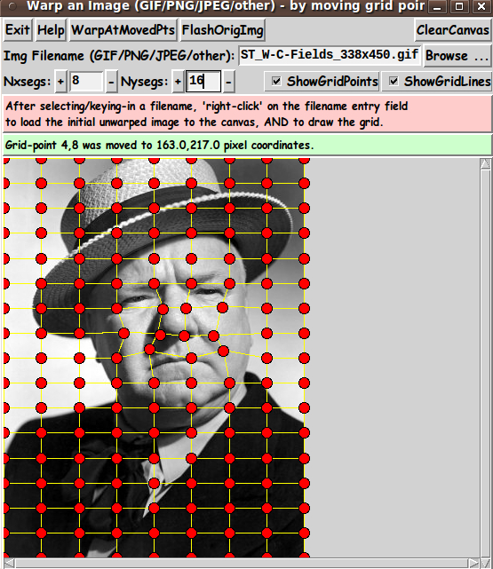
Here is the resulting warp. (I could have made the new nose at the original angle instead of so vertical. Maybe next time.)
And here is an animated GIF made from the original image and a single warped image.

I am relieved that after much, much work, I got it to work.
uniquename 2014mar27 UPDATE
In the 'Possible Enhancements' section above, I indicated that I might add a 'MakeAniGIF' button. I have done that --- in an added '.fRanigif' frame, using an added 'make_aniGIF' proc.
A Delay-time entry widget and a couple of radiobuttons were added to the GUI, in the new '.fRanigif' frame. Image below.
I have updated the 'HELPtext' variable with the following mini-guide:
  To make it easy for the user to make a TWO-IMAGE animated-GIF
  --- from an original image and a warped image --- the GUI
  has a 'MakeAniGIF' button.

  After the user performs a warp, the user can SIMPLY click on
  the 'MakeAniGIF' button. 'Underneath the covers', this utility
  makes two GIF files in a temporary directory --- from the
  original image and the warped image (that are in-memory).

  By default, this utility uses the ImageMagick 'convert' command
  to make an animated GIF from the two GIF files --- using the
  'Delay' parameter on the GUI to determine the length of time
  each image is displayed.

  Alternatively, the user can use the 'gifsicle' command by
  changing the radiobuttons setting on the GUI.

  So that the user does not have to navigate to the temporary
  directory to see the files, the animated GIF is IMMEDIATELY
  shown to the user in animated mode.

  If ImageMagick 'convert' was used, the animated-GIF is shown
  with the ImageMagick 'animate' command.

  If 'gifsicle' was used, the animated-GIF is shown with the
  'gifview' command, which often comes with 'gifsicle'.

  If the animated-GIF file is usable, the user can navigate
  to the temporary directory (defaulted to /tmp) and find
  the '_ani.gif' file there. Move it and/or rename it.
The following image shows the new GUI --- with the new 'MakeAniGIF' button, 'Delay' entry field, and 'convert'/'gifsicle' radiobuttons.
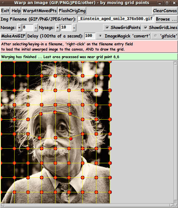
You can see a warped grid and the warped image underneath it --- the result of clicking on the 'WarpAtMovedPoints' button.
Clicking on the 'MakeAniGIF' button created and showed the following animated GIF --- in a fraction of a second.

Even Einstein was surprised when told that one of his predictions was proven true.
I feel that this utility/app is pretty complete now. If I were to enhance it further, I would probably make a new script that put a margin around a loaded image and allowed the user to move the outer-edge grid points --- both inward and outward.
---
Some other 'fun-with-images' scripts that I have donated to this wiki:
* ImageMagnets - a Tk GUI for image processing
* Pointillate Image --- using Tk 'photo' image files (GIF,PGM,PPM,PNG)
* tkMerge2Images - GIF/PNG/JPEG - with image-weighting & image-alignment options
uniquename 2014jun07 UPDATE - Planned Enhancements
I should know by now that I should not make a statement like I did above: "I feel that this utility/app is pretty complete now."
When I think back on the 60-plus scripts that I have contributed to this wiki, almost every script could use some changes, such as
- correcting comments (which are about 95-plus-percent in-sync with the code, but a few percent out of sync)
- adding an 'aRtext' array in which to put text for widgets such as labels and buttons
- making sure all 'expr' statements include braces (for efficient execution)
if not more extensive changes and enhancements.
And this script is no exception. Within a day after posting the update to add a 'MakeAniGIF' button, I realized that the animated GIF was made from only 2 images: the initial image and the warped image.
I realized that I should allow for making a sequence of images, interpolated between those two images, which would allow for making animated-GIF files with a smoother transition between the two images.
In fact, I did that in the GUI that I made about a month later, posted at the page wheeeMorph - to morph 2 images - GIF/PNG/JPEG/other - using a barymetric technique on triangles.
In the 'wheeeMorph' utility, I added an entry widget, next to the 'MakeAniGIF' button, for an 'Nframes' parameter --- to set the number of frames to use in making the animated-GIF (or movie) file.
In that 'wheeeMorph' utility, I used a proc named 'set_grid3' to make a sequence of interpolated grids. I could use a similar proc in this 'tkImageGridWarp' utility, to interpolate between the initial rectangular grid and the user-specified warped grid.
Additionally, in the 'wheeeMorph' utility, I allowed the user to slide grid points along the edges of the image, in making a warped grid. I could add that feature to this 'tkImageGridWarp' utility.
Also, in the 'wheeeMorph' utility, I allowed the user to make a movie file, instead of an animated-GIF file.
So, if I return to this 'tkImageGridWarp' utility someday, I plan to add at least 3 features:
- an option to make a movie file, as well as an animated-GIF file
- an 'Nframes' parameter (and additional procs), to make animated-GIF or movie files including 'intermediate' warped images, between the 2 images (initial and warped)
- an option to slide grid points along the edges of the image, when making the warped grid.