Vector rotations with Bwise
by Theo Verelst
A common thing in math and science is the rotation of a vector over an angle, as most with a math basis knowledge will know, a matrix can be used for the purpose of performing the rotation on a vector.
A rotation matrix is even a very well formed matrix in general with normally excellent invertability and eigenvalue computability.
It is not hard to make a orthogonal and even orthonomal basis for both the column and row space of a 2 dimensional matrix, and we can do so symbolically with simple geometic functions with a single rotation angle as a parameter for each of the 2x2 matrix elements which determines the rotation the matrix performs when multiplied to a vector.
Clear application is computer graphics, but other computations, for instance where complex numbers are used such as in electronics or other solutions of differential equations, also can become more insightfull by clear (simple) vector representations.
Bwise is about BlockWise programming, and also about Tk canvasses with interactions and graphical feedback, so this is a nice example.
Bwise currently latest version: Bwise version 0.34, all in one file, 8.4 compatible [L1 ] .
For all but the first below, the addition from Automatically generate Bwise blocks from procedures is needed (the script portion of that page), and probably it is handy to cut-and-paste [L2 ] (but not needed).
When I've put it all together and extended some more, I'll make a new bwise version, maybe with examples.
I've checked the scripts on this page, and verified that when the script paragraphs are entered into a console or otherwise put on a row, the example on the bottom of the page works without the need for anything else than exactly the specified tcl code, i.e. no special settings or UI interactions are required.
In tcl, without using anything specifically from the Bwise package, except I used the function window, and will use the 'create block' facility of it, the rotation of a 2 dimensional (2 real components obviously quantized to some computer number resolution) vector can be performed by:
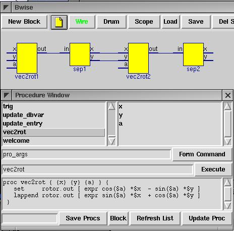
 proc vec2rot { x y a } {
   set     rotor.out [ expr cos($a) *$x  - sin($a) *$y ]
   lappend rotor.out [ expr sin($a) *$x  + cos($a) *$y ]
 }
When this procedure is defined, procs_window from bwise can be used to blockify our procedure. First, refresh the list of procs, then double click vec2rot, and then press the ' block' button on the bottom. First, a block on the canvas will be generated with name 'vec2rot'. When pressed again, serial numbers are added to the name, based on the highest appearing serial number on the canvas thus far. I double clicked and 'del sel' (deleted) the first instance of the block after clicking into existence two more, so I have vec2rot1 and vec2rot2 .
Alternatively, it is possible to script generate the blocks from the above function:
 proc_toblock vec2rot {} vec2rot1
 proc_toblock vec2rot {} vec2rot2
 # move freshly generated block into its place (must do before connect)
 $mc move vec2rot1 -237 -169
 $mc move vec2rot2 -43 -169
The procedure, like any, has only one return value, which is a list.
So we define for the sake of the Bwise canvas we have in mind a seperate block, which splits a 2-long list into elements for to two output pins. We use the newproc bwise proc to generate a 2 output block, possibly using the pro_args functions, which automatically puts arguments in place for the newproc, which gets default arguments except for name and output pin names x and y. I added coordinates to put the blocks on the canvas in a decent position, that's not strictly needed, though, so for the first command it would suffice to eval {newproc {} sep1 in {x y}} .
pro_args newproc {{name {sep1}} {out {x y}} {x {159}} {y {31}} }Gives repeated for sep2):
   newproc {} sep1 in {x y} 40 {} {} 159 31
   newproc {} sep2 in {x y} 40 {} {} 353 31
Either using eval on the pro_args or simply issuing the newproc command a seperator block is created which is given list-split block function code, and connected to the output of the rotation block by either command or UI:
   set sep1.bfunc {set sep1.x [lindex ${sep1.in} 0] ; set sep1.y [lindex ${sep1.in} 1] }
   set sep2.bfunc {set sep2.x [lindex ${sep2.in} 0] ; set sep2.y [lindex ${sep2.in} 1] }
The connections I used were (as generated by gen_netlist):
 connect {} sep2 in vec2rot2 out
 connect {} sep1 y vec2rot2 y
 connect {} sep1 x vec2rot2 x
 connect {} sep1 in vec2rot1 out
The above Bwise representation was made by doing the above twice to create two rotator blocks and list splitters, and by connecting the blocks up and dragging them in place.
Lets define PI, and see if we can make the block sequence work for us by feeding it a vector, specifying angle, activating the block chain, and inspecting the results at the output pins.
set pi [expr 2.0*acos(0)]
The input vector can be set, for instance to (1,0) by editing the fields in the vec2rot1 blocks' data window, called up by right clicking on the block and selecting 'Data'. Or by using the tcl set command to set the pin variables 'by hand':
 set vec2rot1.x 1
 set vec2rot1.y 0
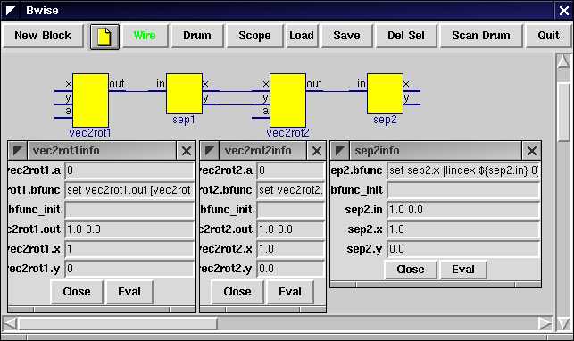
After also entering an angle, for instance 0 (rad), and also entering an angle in the vec2rot2's data window, we can apply 'Funprop' (short for functional propagate, which makes all blocks 'fire' which at some point in the process have all their input pins fed with new data over a connection) to run the whole sequence, which results in the following:
Does that add up? Easily. Graphical inspection makes clear we have entered x1 basis vector into our computation, and requested two 0 rotations of rotations matrix/vector multiplication blocks, and we see at the overall output at sep2 that we get the same vector as x1 as a result. Now lets add some rotation to the chain, for instance a 180 degree rotation in the first block by entering the (numerical) value of PI into the field:
   set vec2rot1.a $pi
   # 3.14159265359
   set vec2rot2.a 0.0
which after issueing
net_funprop vec2rot1
To 'run' the network again results in an output vector of (-1.0 -2.06823111155e-13) which is very close to the vector (-1,0) which is indeed -x1 , the half circle rotated input vector.
We may also want to check how we can rotate followed by inverse rotate by setting
set vec2rot2.a -$pi
and again funpropping the net starting somewhere before or at the vec2rot2 block, which should give us back the first basis vector (1 0), and appears to give (on p4 RH9 linux, but probably pretty much exactly the same on windows, which I used yesterday without any script changes) {1.0 2.53066578395e-25} which is close enough.
Of course other angles work just the same. I've reconstructed this example in a short time from something I'd done before. Now I'll see if I can add some vector graphics, which should look nice on the canvas.
For the next stuff BWise of the last 4 year or so is needed, because of some assumptions on the procedure library.
First we'll add a vector display block, which I did like this:
 newproc {} vecdis1 {x y} {} 100 100
 $mc create line 60 60 105 60 -tag {vecdis1 proc vecdis vector} -fill darkgreen -arrow last
The vector is created assuming the yellow block is created at its default position, and is dragged along when the block is dragged over the canvas. To make sure the vector gets updated when the inputs of the block change, we give the vecdis block a block function which reads the x and Y and redraw the vector (a single line with one arrow point):
 set vecdis1.bfunc { \
  set co [$mc coords [tag_and {vecdis1 block}]] ; \
  set co [list [expr ([lindex $co 0]+[lindex $co 2])/2] [expr ([lindex $co 1]+[lindex $co 3])/2]] ; \
  eval $mc coords [tag_and {vecdis1 vector}]  \
    [lrange $co 0 1] \
    [expr 45.0*${vecdis1.x}+[lindex $co 0]] \
    [expr -45.0*${vecdis1.y}+[lindex $co 1] ] \
 }
this drawing routine assumes the vector to be of length one or smaller, the length is multiplied by 45 to fit in the 100x100 block.
We can make the block transparent (as in the windowdump) by setting the yellow basis block to have no fill:
$mc itemco [tag_and {vecdis1 block}] -fill {}To move the vector block in place before it is connected, to set at the end of the chain:
$mc move vecdis1 441 21
Possibly use script to connect (or use click on two pins 'Wire' button):
 connect {} sep2 x vecdis1 x
 connect {} sep2 y vecdis1 y
When our new vector display block is connected up with x and y of the output of the rotators and the list split, we can visualize the result of the rotations of the vector at the input of the first rotator (1,0):
On the left of the image a seperate window with 2 sliders can be seen, which can be generated from the bwise library, and which I coupled with the 2 angle inputs of the rotation blocks. The slider send routine (part of bwise) is changed to not send over a socket channel, but update the variables, while the update which is triggered by the release of any slider activated the chain of blocks with a net_funprop procedure call.
 proc slidsendupdate { } {
 #   send update
   net_funprop vec2rot1
 }

 proc slidsend { {n} {v} } {
  set v [expr $v*2.0*2.0*acos(0)/360]
  switch $n phi {
     uplevel #0 "set vec2rot1.a $v"
  } theta {
     uplevel #0 "set vec2rot2.a $v"
  }
 }


 sliders {{phi 180} {theta 180}}
The number 180 is used to have not to many degrees on the whole scale, you could change to 360 or another number, and also the slider window can be resized.
TV (May 11 2004) I've changed the 'connect' commands to have {} as first argument, to let wires be named automatically. Sometimes when messing with bwise network scripts, absolute wire names can cause errors, because they are usually not visible, and overlapping names can give strange errors.


