Blend2d
ABU 25-Sep-2026 - Blend2d 1.9 released (see the CHANGES section)
- Version 1.9 restores usability on MacOS with Tcl/Tk 9.0.2 or later.
TclTk binding for Blend2d has been released.
The package contains prebuilt binaries for Win-x64, Linux-x64, and MacOS (Apple-Intel and apple-Silicon).
Within the package, you can find a reference manual and a few basic demos.
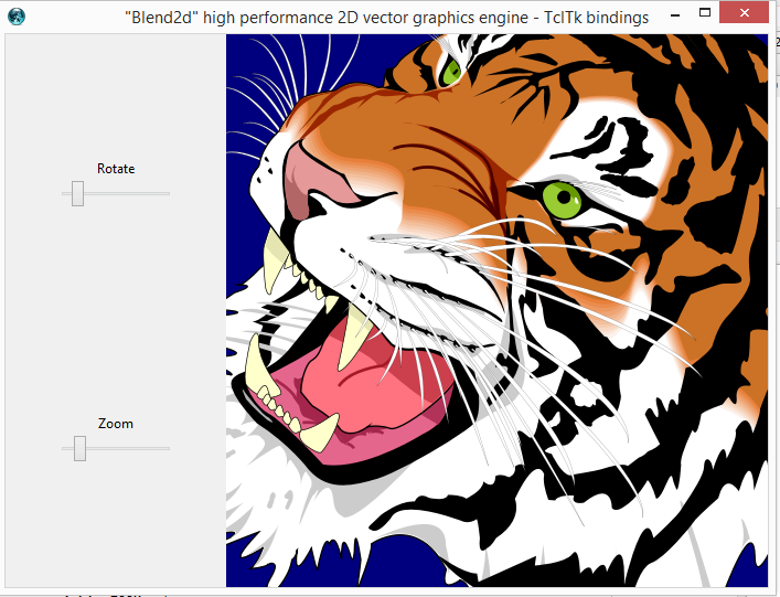
For starters, take a look at some demo screenshots
- Blend2d Gallery (old wiki page)
- [L1 ] (new ABU gallery)
The full pack of demos (more than 100 scripts) is delivered separately. Take a look at the Gallery https://abu-irrational.github.io/tclBlend2d-Gallery and then download all the source files from
Pictures
CHANGES
Blend2d 1.9 - 2026-09-24
- NEW FEATURES
- new method "BL::Font dup"
- new method "BL::Font maxAscentDescent"
- added a folder "toolkit" containing some utilities for developing some apps/demo
- package geom::kit 0.1
- package BL::Path::kit 0.1
- package BL::canvas
- when a blend2d image is resized, a virtual event <<Resized>> is sent to the widgets holding the image.
- BL::canvas - a simple but efficient way to display a blend2d image
- new method BL::Surface finalTransform and inverseTransform (used main by BL::canvas)
- Doc-FIX
- Corrected the signature of the BL::Path "ellipticArc_To" method.
- BUGFIX
- The temporary surface for the "shadow" filter needs to be cleaned.
- It's incredible it worked so far - Now fixed.
- Cross compilation on MacOS : On MacOS Silicon you cannot cross-build for MacOS Intel. Now fixed
- On MacOS with Tk 9.0.3 or later, the image does not display. Now fixed.
- The temporary surface for the "shadow" filter needs to be cleaned.
Blend2d 1.8 - 2026-05-30
- NEW FEATURES
- method "BL::Surface save" extended with options -crop -scale -width -height
- new command BL::colorToTkcolor
- enhanced filter "innershadow" : added option "-dxy" for the translation of the Shadow.
- new method BL::Surface transparencyStyle" to reveal the semi-transparent areas with a chessboard-like pattern.
- added new filter "tint"
- added new filter gradientmap
- filter bw - added option -lut for tonal adjustment
- new method "BL::Suface histogram .."
- BUGFIX
- Previously, the luminance for the "bw" filter was computed with RED and BLUE exchanged; Now fixed.
- Syntax error when calling "$sfc filter morphDilation .." or "$sfc filter morphErosion .." Now fixed.
- demo/sample03.tcl - texture.jpeg not found . Now fixed.
Blend2d 1.7 - 2025-11-05
- Blend2d-core aligned with Blend2d 0.21.2
- NEW FEATURES
- new method "BL::Surface fill&stroke"
- BL::FontFace DEPRECATED ...
- extended BL::Font create/new with alternative parameters (BL::FontFace non more required)
- new method BL::Font configure/cget methods.
- new method "BL::Font face metrics"
- new method "BL::Font face flags"
- BUG-FIX
- A very old (and rare) bug involving the duplication of the context options after a BL::Surface "dup" or BL::Surface resize
- .. some context options implicitly depending on other context options (ed. patter/gradients depends on the transformation matrix), were not restored in the correct oder, Now FIXED.
- Apparent bug: Filters crop the border - Root Cause: DirtyArea wrongly computed for stroked paths and global scaling . Now FIXED
- Wrong error message when "BL::Font new/create" is called without args. Now FIXED
- A very old (and rare) bug involving the duplication of the context options after a BL::Surface "dup" or BL::Surface resize
- Doc-FIX
- Corrected the signature of the BL::Font "face" method.
Blend2d 1.6 - 2025-09-22
- Updated build procedure for Apple-Silicon
- no more Universal build: Two distinct builds for Apple-Intel and Apple-Silicon.
- NEW FEATURES
- new method "BL::Surface scroll"
- new method "BL::Path hitTest"
- new method "BL::Path vertices …
- new methods "Mtx::sincos_rotation" and "Mtx::sincos_rotate"
- new methods "Mtx::bestFit" and BL::Path::bestFitTo
- new utilities "BL::box2rect" , "BL::enlargedrect"
- extended the RADIAL gradient with an optional parameter.
- new morphological filters: erode, dilate, open, close + stringifyStructuringElement
- new filter innershadow
- Doc-FIX
- Added the "Svgdoc::bbox" method.
- Corrected the signature of the BL::Path::fitTo method.
Blend2d 1.5 - 2025-03-27
- Blend2d-core aligned with Blend2d 0.12.0
- New FEATURES
- new method "BL::Surface addimage"
- BL::Font::textmetrics - reintroduced the boundingBox detail.
- added general support for multi-line text:
- see "BL::text" and all the BL::Font methods
- added option -justify for disposing multi-line text (LEFT,CENTER,RIGHT)
- Internals:
- Optimized Surface resizing ( do nothing if format has not changed )
Blend2d 1.4 - 2025-01-31
- Blend2d-core aligned with Blend2d 0.11.5
- New FEATURES
- Extended Conical gradient, supporting an optional repeat parameter.
- Extended method "BL::Font glyphs", extracting some placement info, too
- New method "BL::Font face" returns details from its related BL::FontFace
- New method "BLPath::empty" returns true/false if the BLPath bbox is empty.
- New methods: loadmask, savemask, invertmask, fillmask
- Optimized computation of dirty-Area and refresh area
- Errata corrige in tclBlend2.man
- the growing demo directory has been removed from the distribution. Only few old demos are left.
- All the old and future demos will be available as a separate package.
- DOC Fix
- doc updated with the new features
- curvature returned by the "BL::Path contour" method is a signed curvatures. Previously it was stated it's always >= 0.
- BUG Fix
- method "glyphs" does not take in account ligatures. Now Fixed.
- BL::Path::contours - op should be "tangentAt" (instead of "TangentAt"). Now Fixed
- filters (blur, bw, ...) should works only on 32-bit images. Now Fixed
Blend2d 1.3.1 - 2024-08-21
- No API changes but added compatibility for Tcl9.
- This release contains dll/so both for Tcl8 and Tcl9.
- Adapted scripts to be Tcl9 compatible.
- Note: sample105-SVGmoby.tcl requires an (external) version of tdom, compatible with Tcl9.
- BUG FIX
- addSVGpath method now accepts A (arc) commands written in compact form (no spaces or commas). FIXED. Added a new test-case
Blend2d 1.3 - 2024-07-11
- Blend2d-core aligned with Blend2d 0.11.4
- New Features
- Added support for load/save QOI graphic files.
- Added new command Mtx::quadtoquad for perspective transform.
- extended BL::Path transform to accept a 3x3 matrix, too.
- new commands for mixing colors: HSBblend, HSLblend
- Added new class BL::SvgDoc for loading a full SVG-file; this svgfile can be rendered with the new "paint" method.
- Added commands BL::loadsvgfonts and BL::loadedSVGfonts
- BUG FIX
- Method Method_arcTo : missing control for optional parameters. Fixed
- Memory leaks with "BL::pattern filename ...". Fixed
- BUGFIX for "BL::spline ...":
- a command like "BL::spline {-1 0} ..other points..." is misinterpreted, producing an incorret error message like the following: "syntax error - unrecognized option "-1 0".
In general if BL::spline has no options, then the minus sign of the first point, is erroneously interpreted as the start of an option "-", and then the error .. FIXED
- Man-page for "BL::spline ..." updated with details of the -alpha option (option available in 1.2 but never documented).
Blend2d 1.2 - 2024-03-12
- Blend2d-core aligned with Blend2d 0.10.6 (Patch 10-Mar-2024)
- Breaking changes
- the "contour" method has been extended - for some corner cases, output format has changed.
- New Features
- Starting with tcltk 8.6.14, a tk-core bug has been fixed
- "Aqua: XPutImage() swaps red and blue channels"
- Therefore, from that tcltk release, blend2d works on MacOS, too.
- BL::Path: added method "reverse"
- BL::Path: added method "contours"
- BL::Path: extended method "contour"
- - length of contours and length of single b-curves
- - subdivision of contours (uniform length and uniform-t)
- - curvature
- - possible incompatibility with previous API
- Added HSL<-->RGB color conversion.
- Mtx: added fixed point for xreflection and yreflection,
- Mtx: added xreflect
- Starting with tcltk 8.6.14, a tk-core bug has been fixed
- BUG FIX
- readFromTkphoto & writeToTkPhoto
- - In some corner cases, incorrect result for the destination region
- - it MUST have always the same size of the (clipped) source region.
- readFromTkphoto:
- - tkphoto with transparencies were not properly handled:
- - transparent (or semi transparent) pixels MUST be *blended* with the surface
- - Previously all pixels from tkphoto were simply copied, including the transparent pixels).
- readFromTkphoto & writeToTkPhoto
- DOCUMENTATION
- Updated with a full description of the new features.
- more detailed documentation for methods "readFromTkphoto", "writeToTkphoto"
- TEST-SUITE
- Updated to cover all new features
- DEMOS
- Added a lot of new demos.
Blend2d 1.1.1 - 2023-10-31
- Blend2d-core aligned with Blend2d 0.10.5 (Patch 28-Oct-2023)
- Breaking changes
- gradients: CONICAL renamed as CONIC.
- Method "BL::Font::textmetrics no more provide the boundingBox details. See the new method "textbox".
- New Features
- Added new geometry BL::spline
- Added new geometry BL::textbox
- Enhanced BL::text with -anchor option
- Added method BL::Font::textbox
- Added method BL::font::metrics
- Added method BL::font::textmetrics
- Added method BL::Surface::applyTransform
- Added option "-transformation" to the fill/stroke methods.
- Added filter "bw" (black&white)
- BUG FIX
- Removed memory leaks in method "add" of BLPath
- DOCUMENTATION
- Updated with a full description of the new features.
- .. plus a lot of corrections.
- TEST-SUITE
- Updated to cover all new features
Blend2d 1.0.1 - 2023-06-12
- Version 1.0.1 (based on the core Blend2d library ver 0.10.0)
- BUGFIX
- Shadow filter: temporary surface too large in some cases.
- FIXED: DirtyArea should be clipped against the base surface.
- FIX
- Added stackblur.c /.h in SVN repository
- Added demos:
- sample111.tcl (updated, enhanced)
- sample112 (new)
- sample113 (new)
- sample114 (new)
Blend2d 1.0 - 2023-04-15
- Version bumped to 1.0 (based on the core Blend2d library ver. 0.8)
- New BL::Surface methods:
- dup
- rawcopy
- blur
- filter (blur, shadow)
- New BL::Path methods:
- newStrokedPath
- BL::Path enhancements
- method "add" now accepts also BL::text ... geometries.
- Text is automatically converted in a set of curves and added to BL::Path. This can be used for transforming a text in a SVG path ..
- BUGFIX
- option -stroke.dashArray does not accept empty array. Now FIXED
- option -stroke.join does not accept ROUND as value. Now FIXED
- method "addSVGpath" not working with the "a" command. Now FIXED
- method "addSVGpath": type-error for internal method "smoothQuaTO. Now FIXED
Blend2d 1.0b2 - 2020-09-03
- BugFix in Blend2d core (smoothCubicTo)
- DocFix: method "BL::Path lineTo" accepts a sequence of points.
- Extensions: method "BL::Path quadTo" accepts a sequence of 2*N of points.
- Extensions: method "BL::Path cubicTo" accepts a sequence of 3*N of points.
- Extensions: method "BL::Path smoothQuadTo" accepts a sequence of points
- Extensions: method "BL::Path smoothCubicTo" accepts a sequence of 2*N of points
- Added method "BL::Path addSVGpath"
- updated docs and tests
- Added demos
- sample104-handmade lines
- sample105-SVGmoby
Blend2d 1.0b1 - 2020-08-12
- First beta release
INTRODUCTION
TclBlend2d is a Tcl package for working with the Blend2d graphics engine.
Blend2d is an open source, high quality, high-performance vector graphics engine
TclBlend2d is a multiplatform binary package including Blend2d library for Windows and Linux; MacOS support is planned.
Images created with TclBlend2d can be saved as BMP files, or exchanged with the tk-photo images.
TclBlend2s provides also a new type of tk-image (named "blend2d") you can embed in your widgets much like a tk-photo image.
You can draw on a "blend2d" tk-image and instantly see the changes in the widgets that have this image attached.
TclBlend2d closely matches the Blend2d C++ API with the exception of cases where a more Tcl-ish way is more appropriate.
DEFINITIONS and CONCEPTS
SURFACES
The main concept of TclBlend2d is the Surface.
A Surface comes with an internal pixmap (32bit depth, with alpha support) and holds all of the graphics state parameters that describe how drawing is to be done. This includes parameters like the current line width, the current color (or gradient), a 2D transformation matrix and many other things.
It allows the actual drawing function to take fewer arguments to simplify the interface.
A Surface implements an immediate-mode rendering; there's no concept of 'scene' or display-list like in the tk-canvas widget; if you want to delete or move a part of the pixmap, you should erase everything and restart drawing from the beginning.
The whole graphic-state can be saved on an internal Surface stack. Any subsequent changes to the graphics state can then be undone quickly by simply restoring the previous graphics-state.
TclBlend2d provides support for simple and complex geometrical entities.
Among the simple geometrical entities, you can find lines, arcs, (rounded) rectangles and many others.
A Path is a complex geometrical entity made of lines and curves (quadratics and cubics Bezier's curves).
A Surface provides just two methods for drawing the geometrical entities: fill and stroke. A geometrical entity can be stroked or filled with a style, i.e a solid color, a gradient, or a pattern.
COLORS, STYLES, and COMPOSITION-OPS
When you stroke/fill a geometrical entity, you are not limited to use an uniform color; when you do a stroke/fill, you apply a style. A style can be
- a uniform color (with alpha transparency)
- a gradient
- a pattern (i.e. a bitmap)
Styles may have their own alpha-transparency, and when you do a fill/stroke, pixels are blended with the pixels already stored in the internal pixmap.
You can set a composition op to control how the new colors are blended with the destination.
MORE on STROKING
TclBlend2d provides support for controlling how a (complex) stroke is rendered: caps, joins, miter, dashes, ...
COORDINATE SYSTEMS and TRANSFORMATIONS
By default the coordinates you specify (user-coords) coincide with the coords of the internal pixmap (pixmap-coords), being (0.0 0.0) the top-left corner.
You can set and combine a transformation matrix (translation, rotation,scale,...), then all the following coordinates you specify with the fill/stroke methods are accordingly multiplied.
These transformations are part of the whole Surface's graphics-state and then they can be pushed on the Surface's stack.
TEXT
TclBlend2d provides support for simple text layout. It can also parse and extract glyphs from the most common font-files.
Glyphs can also be transformed in Path (i.e. set of curves) and then analytically manipulated in terms of contours and single curves.
IMAGES
TClBlend2d has builtin support for reading BMP, PNG, QOI and JPG files.
Currently, support for writing is limited to BMP, PNG, QOI but you can save the generated image in a tk-photo and then save it in any other format ...
Note that you can import/save just a part of an image (a tk-photo or another Surface), and when you import an image in a Surface, the image is transformed based on the current transformation matrix, i.e. it is properly scaled/rotated.
This concludes this short introduction to the basic features and concepts for working with TclBlend2d.
For further details, read the Getting-started section, look at the demos included with the package, an read the reference manual...
Getting Started
How to create and view an image generated with blend2d ?
Let's create a very simple image with Blend2d
    package require Blend2d
    BL::Surface create mySfc
    mySfc clear
    mySfc fill [BL::circle {200 200} 50] -style [BL::color orange]
    ... you got the idea ...
then we could:
- save it in a file (currently only .BMP is supported)
mySfc save "./image01.bmp"
- copy the image in a tk-photo
    image create photo photo1
    mySfc writeToTkphoto photo1
... and then embed photo1 in a widget, or save it in a file ...
But we could also create a totally new kind of image that can be embedded in a widget and manipulated in real-time...
You already know how to display a tk-photo in a widget like a canvas or a label. tclBlend2d provides a new type of image named "blend2d".
image create blend2d mySrf1
"mySrf1" is both a new image and a BL::Surface object (i.e. a command). So, you can embed this image in a widget
    label .a -image mySrf1
    pack .a
and then draw on "mySrf1" ...
    mySrf1 clean
    mySrf1 fill [BL::circle {100 100} 80] -style [BL::color red]
    ...`
You can continue to draw in mySrf1, and instantly see the results in the label-widget.
Reference Manual - Blend2d 1.9
tclBlend2d 1.9 tclBlend2d Tcl meets Blend2d
Tcl meets Blend2d
SYNOPSIS
package require Tcl 8.6
package require Blend2d ?1.9?
- BL::Surface create sfcName ?options?
- BL::Surface new ?options?
- sfcName destroy
- sfcName dup
- BL::Surface names
- sfcName configure
- sfcName cget optionName
- sfcName configure optionName
- sfcName configure optionName optionValue ?optionName optionValue ...?
- sfcName push
- sfcName pop
- sfcName stacksize
- sfcName reset
- BL::rgb RR GG BB ?alpha?
- BL::color colorName ?alpha?
- HSB hue sat brightness ?alpha?
- HSL hue sat lightness ?alpha?
- BL::gradient type values stopList ?options?
- BL::pattern sfcName|filename ?options?
- BL::line {x0 y0} {x1 y1}
- BL::polyline {x0 y0} {x1 y1} ?{x2 y2} ....?
- BL::polygon {x0 y0} {x1 y1} ?{x2 y2} ....?
- BL::box {x0 y0} {x1 y1}
- BL::rect x y w h
- BL::roundrect x y w h rx ?ry?
- BL::circle {cx cy} r
- BL::ellipse {cx cy} rx ry
- BL::arc {cx cy} rx ry start sweep
- BL::pie {cx cy} rx ry start sweep
- BL::chord {cx cy} rx ry start sweep
- BL::text {x y} font text ?-anchor anchor? ?-justify mode?
- BL::textbox {x y} font text ?-anchor anchor? ?-justify mode?
- BL::spline ?-alpha a? ?mode? {x0 y0} {x1 y1} ?{x2 y2} ....?
- sfcName stroke geometry ?options?
- sfcName fill all|geometry ?options?
- sfcName fill&stroke geometry ?options?
- sfcName paint svgName ?options?
- sfcName clear ?options?
- sfcName flush
- sfcName size
- sfcName applyTransform mtx
- sfcName userToMeta
- sfcName finalTransform
- sfcName invertedTransform
- sfcMask loadmask filename channel
- sfcMask savemask filename
- sfcMask invertmask
- sfcName fillmask xy sfcMask
- BL::Path create pathName
- BL::Path new
- pathName destroy
- pathName dup
- BL::Path names
- pathName add geometry ?geometry ...? ?options?
- pathName newStrokedPath ?stroke-options?
- pathName addSVGpath dataString
- pathName apply matrix
- pathName fitTo {x y w h}
- pathName bestFitTo {x y w h}
- pathName moveTo point0
- pathName lineTo point ?point ...?
- pathName quadTo p1 p2 ?p1 p2...?
- pathName cubicTo p1 p2 p3 ?p1 p2 p3...?
- pathName smoothQuadTo p2 ?p2...?
- pathName smoothCubicTo p2 p3 ?p2 p3...?
- pathName arcQuadrantTo point1 point2
- pathName arcTo pointC pointR start sweep ?-moveto boolean?
- pathName ellipticArcTo pointR rotation largeArcFlag sweepFlag point1
- pathName close
- pathName reset
- pathName shrink
- pathName bbox
- pathName empty
- pathName reverse
- pathName view
- pathName vertices count
- pathName vertices all
- pathName vertices index
- pathName vertices startIdx lastIdx
- pathName hitTest p
- pathName contours ?count?
- pathName contour tolerance ?value?
- pathName contours reset
- pathName contour i|* ?count?
- pathName contour i|* length
- pathName contour i|* isclosed
- pathName contour i|* atlength rLen curveOP
- pathName contour i|* t-subdivision N curveOP
- pathName contour i|* l-subdivision N curveOP
- pathName contour i|* j|* length
- pathName contour i|* j|* atlength rLen curveOP
- pathName contour i|* j|* curveOP t
- pathName contour i|* j|* t-subdivision N curveOP
- pathName contour i|* j|* l-subdivision N curveOP
- BL::Svgdoc create pathName SVG-file
- BL::Svgdoc new SVG-file
- BL::Svgdoc bbox
- pathName destroy
- BL::Svgdoc names
- BL::loadedsvgfonts
- BL::loadsvgfonts font-file ?font-file ...?
- DEPRECATED -- BL::FontFace create faceName fontfile ?faceIdx?
- DEPRECATED -- BL::FontFace new fontfile ?faceIdx?
- DEPRECATED -- faceName destroy
- DEPRECATED -- BL::FontFace names
- DEPRECATED -- faceName details
- BL::Font create fontName -fromfile fontfile ?-faceindex index? ?-fontsize size?
- DEPRECATED -- BL::Font create fontName faceName fontsize
- BL::Font new -fromfile filename ?-faceindex index? ?-fontsize size?
- DEPRECATED -- BL::Font new faceName fontsize
- fontName destroy
- fontName dup
- BL::Font names
- fontName configure
- fontName cget optionName
- fontName configure optionName
- fontName configure optionName optionValue ?optionName optionValue ...?
- fontName face
- fontName face details
- fontName face flags
- fontName face metrics
- fontName metrics
- fontName textmetrics string
- fontName textbox xy text ?options?
- fontName maxAscentDescent text
- fontName glyphs someText
- fontName glyphs someText -withadvance bool ?-justify mode?
- fontName glyph glyphIdx
- sfcName blur radius ?-rect {x y w h}?
- sfcName bw ?-luma {r g b}? ?-lut list of grays? ?-rect {x y w h}?
- sfcName tint color ?-rect {x y w h}?
- sfcName gradientmap gradientStops ?-rect {x y w h}?
- sfcName morphErosion ?-kernel {shape rx ry}? ?-rect {x y w h}?
- sfcName morphdilation ?-kernel {shape rx ry}? ?-rect {x y w h}?
- sfcName morphOpening ?-kernel {shape rx ry}? ?-rect {x y w h}?
- sfcName morphClosing ?-kernel {shape rx ry}? ?-rect {x y w h}?
- sfcName filter filterType ?filter-args? script
- sfcName scroll dx dy ?-rect {x y w h}?
- sfcName histogram A|R|G|B ?-rect {x y w h}?
- sfcName load filename
- sfcName addimage filename ?options?
- sfcName save filename ?-format file-format? ?-crop rectangle? ?-scale factor | -width dx | -height dy?
- sfcName copy srcSurface ?-from {x0 y0 w h}? ?-to {xp yp}? ?-compop op? ?-globalalpha alpha?
- sfcName copy srcSurface ?-from {x0 y0 w h}? ?-to {x y w h}? ?-compop op? ?-globalalpha alpha?
- sfcName rawcopy srcSurface ?-from {x0 y0 w h}? ?-to {x y w h}? ?-compop op? ?-globalalpha alpha?
- sfcName readFromTkphoto tkphoto ?-from {x0 y0 w h}? ?-to {x0 y0}?
- sfcName writeToTkphoto tkphoto ?-from {x0 y0 w h}? ?-to {x0 y0}?
- image create blend2d ?name? ?options?
- sfcName transparencyStyle ?how?
- BL::classes
- BL::classinfo objectName
- BL::codecs
- BL::enum
- BL::enum category
- BL::libinfo
- BL::platform
- Mtx::identity
- Mtx::MxM M1 M2
- Mtx::determinant M
- Mtx::invert M
- Mtx::PxM P M
- Mtx::multiPxM Points M
- Mtx::P-P P1 P2
- Mtx::VxM V M
- Mtx::translation dx dy
- Mtx::scale sx ?sx? ?C?
- Mtx::rotation angle radians|degrees ?C?
- Mtx::sincos_rotation sinTheta cosTheta ?C?
- Mtx::skew sx sy
- Mtx::xreflection ?x0?
- Mtx::yreflection ?y0?
- Mtx::translate M dx dy
- Mtx::post_translate M dx dy
- Mtx::scaling M sx sy ?C?
- Mtx::post_scaling M sx sy ?C?
- Mtx::rotate M angle radians|degrees ?C?
- Mtx::sincos_rotation M sinTheta cosTheta ?C?
- Mtx::post_rotate M angle radians|degrees ?C?
- Mtx::xreflect M ?x0?
- Mtx::yreflect M ?y0?
- Mtx::quadtoquad quad1 quad2
- BL::colorToTkcolor blColor
- HSB h s b ?alpha?
- RGB2HSB 0xAARRGGBB
- HSBblend hsb1 hsb2 t
- HSL h s l ?alpha?
- RGB2HSL 0xAARRGGBB
- HSLblend hsl1 hsl2 t
DESCRIPTION
Package Blend2d integrates the Blend2d vector engine in Tcl/Tk. Blend2d is an open source, high-quality, high-performance vector graphics engine. Blend2d is a binary package, distributed in a multi-platform bundle, i.e. it can be used on
- Windows 64 bit
- Linux 64 bit
- MacOS 64 bit (Apple-Intel and Apple-Silicon)
Just an example to get the flavor of how to use Blend2d:
    # draw a circle ...

    package require Blend2d
    set sfc [BL::Surface new]
    $sfc clear
    $sfc fill [BL::circle {150 150} 100] -style [BL::color orange]
    $sfc save "./image01.bmp"
    $sfc destroy
Blend2d with and without Tk
You can run Blend2d from a tclsh interpreter, without loading Tk. The following command
package require tclBlend2d
can be used in a tclsh interpreter to load the package without requiring Tk support. You will be still able to generate and save images, but of course, some subcommands related to Tk won't be available. The command
package require tkBlend2d
loads the full package (and requires Tk). Note that
package require Blend2d
is equivalent to
package require tkBlend2d
BL::Surface and the graphics state parameters
The main concept of Tcl-Blend2d is the Surface. A Surface comes with an internal framebuffer (32bit depth, with alpha support) and holds all of the graphics state parameters that describe how drawing is to be done. This includes parameters like the current line width, the current color (or gradient), a 2D transformation matrix and many other things. A Surface can be created with the following commands
- BL::Surface create sfcName ?options?
- creates a new instance of the class BL::Surface called sfcName. Options can be set at creation time, or later with the configure method.
- BL::Surface new ?options?
- creates a new instance of the class BL::Surface returning a new unique sfcName. Options can be set at creation time, or later with the configure method.
- sfcName destroy
- destroys sfcName. Note that in general any oo-object like sfcName should be explicitly destroyed
- sfcName dup
- duplicates sfcName. Return a new BL::Surface.
Note: the full stack of options is not duplicated; only the current options are duplicated.
- BL::Surface names
- returns the list of all the currently allocated surfaces. The whole set of Surface's options is also called the drawing state.
A drawing state consists of
- the 2D transformations that have been applied (i.e. translate, rotate, and scale ... see below),
- the current values of various attributes controlling how to fill and how to stroke all the basic and complex geometric entities, and it can be manipulated with the cget/configure methods.
- sfcName configure
- returns a list with all the valid options and their values.
- sfcName cget optionName
- returns the current value of the option optionName. Raise an error if optionName is not a valid option.
- sfcName configure optionName
- returns a list with two values: the named option and its value. Raise an error if optionName is not a valid option.
- sfcName configure optionName optionValue ?optionName optionValue ...?
- modifies all the named options with the specified values. Raise an error if any optionName is not recognized or its optionValue is not valid; in this case, no option is modified.
Surface options are:
- -threads count
- If count is >=1 then all the rendering commands are queued and executed by worker-threads when needed (i.e. before exporting an image or, if the surface is a Tkimage, in the event-loop) Default is 0 (i.e all the rendering commands are run immediately (synchronous mode)).
- -format {dx dy {?PRGB32 | XRGB32?}}
- sets the size (in pixels) and type of the internal framebuffer.
WARNING: When user sets a new -format, the previous content of the framebuffer is lost, and the new framebuffer is uninitialized (it contains garbage). It is user's responsibility to clean it or to properly restore the previous contents. Default is {400 400 PRGB32}
- -matrix matrix
- matrix defines the affine transformations that will be applied to the next geometric entities specified with the "fill" or "stroke" operations See the section "Affine Matrix" for more details. Default is {1.0 0.0 0.0 1.0 0.0 0.0} (Identity matrix)
- -metamatrix
- This is a readonly option.
Meta matrix is a core transformation matrix that is normally not changed by transformations applied to the context. Instead, it acts as a secondary matrix used to create the final transformation matrix from meta and user matrices. Meta matrix can be used to scale the whole context for HI-DPI rendering or to change the orientation of the image being rendered, however, the number of use-cases is unlimited. To change the meta-matrix you must first change user-matrix and then call the userToMeta method, which would update meta-matrix and clear user-matrix.
- -compop compositionOp
- defines how colors should be blended. For further details try googling "Porter-Duff composition" or "Alpha composition". Default value is SRC_OVER.
- -globalalpha alphaValue
- defines a global alpha value. alphaValue should be between 0.0 (transparent) and 1.0 (opaque). Default value is 1.0
- -fill.style style
- defines the style to be used for filling. style can be a solid-color (with alpha transparency), a gradient, or a pattern ... Default is 0xFF000000 (Opaque Black).
See the "Setting a style" section below.
- -fill.alpha alphaValue
- defines the alpha value for fill operations. alphaValue should be between 0.0 (transparent) and 1.0 (opaque). Default value is 1.0
- -fill.rule mode
- defines how to fill intersecting curves. Default is NON_ZERO
- -stroke.style style
- defines the style to be used for stroking. style can be a solid-color (with alpha transparency), a gradient, or a pattern. Default is 0xFF000000 (Opaque Black) See above notes for -fill.style
- -stroke.alpha alphaValue
- defines the alpha value for stroke operations. alphaValue should be between 0.0 (transparent) and 1.0 (opaque). Default value is 1.0
- -stroke.width width
- defines the width of the strokes (outlines). Default value is 1.0. Note that the stroke width is scaled according to the current matrix transformation. If you want a constant width, independent of the current scale factor, you should set the option -stroke.transformorder to BEFORE.
- -stroke.dashoffset offset
- defines the offset on the rendering of the associated dash array. Default is 0.0
- stroke.join mode
- defines how the junction point of two consecutive segments will be stroked. Default is MITER_CLIP
- -stroke.miterlimit value
- defines the limit on the ratio of the miter length to the stroke-width used to draw a miter join. When the limit is exceeded, the join is converted from a miter to a bevel. Default is 4.0.
- -stroke.cap capMode
- -stroke.cap {startCap endCap}
- capMode specifies how to render the extremities of the stroke. capMode may be a list of two values to specify the startCap and the endCap separately. Default is {BUTT BUTT}
- -stroke.transformorder mode
- With the default mode AFTER the stroke width will be scaled according to the current transformation matrix. If mode is set to BEFORE, the stroke width won't be scaled. The whole drawing-state is stored on an internal stack, and you can inspect, save, and restore the whole drawing state (i.e. all the options) with just the following commands:
- sfcName push
- saves the current graphic-state on the sfcName's internal stack.
- sfcName pop
- pops the graphic-state from the sfcName's internal stack. Raise an error if stack is empty.
- sfcName stacksize
- returns the size of the sfcName's internal stack (i.e. number of saved graphic-states)
- sfcName reset
- resets the whole surface's graphic-state, including the internal stack. All the options (but -format and -threads) are reset to their default values.
Setting a style
There are 3 types of styles you can set for strokes and fills: SOLID, GRADIENT, PATTERN
- A SOLID style is a uniform color (with optional alpha transparency). It can be specified as a simple hex number in 0xAARRGGBB format, 0xFFFF0000 is red, 0xFF0000FF is blue, or through the following commands:
- BL::rgb RR GG BB ?alpha?
- returns a 0xAARRGGBB color by combining the RR GG BB and the (optional) alpha arguments.
RR, GG, BB are integers 0..255 (best expressed as 0x00..0xFF), alpha is an optional parameter ranging from 0.0 (transparent) to 1.0 (opaque). Default alpha is 1.0
- BL::color colorName ?alpha?
- returns a 0xAARRGGBB color by combining the colorName (as the symbolic names recognized by Tk) and the (optional) alpha arguments.
colorName is a color name (e.g "lightblue") or a numeric-color like #rrggbb, alpha is an optional parameter ranging from 0.0 (transparent) to 1.0 (opaque). Default alpha is 1.0
- HSB hue sat brightness ?alpha?
- HSL hue sat lightness ?alpha?
- These are alternative ways to specify a color (HSB/HSL model).
See the "HSB/HSL color models" section at the end for more details.
- A GRADIENT can be specified with the following syntax:
- BL::gradient type values stopList ?options?
- type should be one of the following values: LINEAR, RADIAL, CONIC
- values is a list of parameters (depending on type)
- for LINEAR: {x0 y0 x1 y1}
- for RADIAL: {x0 y0 x1 y1 r0 ?r1?}
- for CONIC: {x0 y0 angle ?repeat?}
- stopList is a list of offset and colors (at least two pairs of offset colors)
- offset is a number between 0.0 and 1.0
- color can be expressed as an hex number (0xAARRGGBB) or with the above cited BL::rgb , BL::color, HSB, HSL commands.
- options are:
- -mode extendMode
- defines how to extend or repeat the style outside the defined region. Default is PAD. See command "BL::enum EXTEND_MODE" for valid values.
- -matrix mtx
- defines an auxiliary 2D transformation that should be combined with the current transformation matrix. Gradient example:
    # define an oblique LINEAR gradient
    set gr1 [BL::gradient LINEAR  {0 0 400 400}  [list  0.0 [BL::color lightblue]  0.8 [BL::color blue] 1.0 [BL::rgb 0 0 0 0.1]]  ]
    $sfc fill [BL::circle {200 200} 100] -style $gr1
- A PATTERN can be specified with the following syntax:
- BL::pattern sfcName|filename ?options?
- defines a pattern based on another source bitmap, i.e a SfcName, or an external JPEG,PNG,BMP,QOI filename.
Valid options are:
- -mode extendMode
- same as for BL::gradient
- -matrix mtx
- same as for BL::gradient
- -from {x y w h}
- defines the pattern based on a rectangular subregion of the srcBitmap. x, y, w,h are pixel coords (integer coords)
Geometric types
Blend2D provides both simple geometric types ( line, rectangle, circle ....) and complex geometric types (Path). The main difference between simple and complex geometry types derives from their implementation. Although all the geometric types could be implemented as oo-classes, this will tend to develop programs difficult to maintain, since in Tcl oo-objects should be explicitly destroyed. Therefore most of the following commands for building geometric types don't return oo-objects but simple tcl-lists/dictionaries, that are automatically disposed when they go out of scope. Currently, just two complex geometry-types (BL::Path and BL::Svgdoc) are implemented as oo-class, (and then it's programmers's responsibility to explicitly destroy it). A simple example for drawing a simple geometry is
$sfcName fill [BL::box {0 0} {120 175.8}]
The supported simple-geometries are:
- BL::line {x0 y0} {x1 y1}
- BL::polyline {x0 y0} {x1 y1} ?{x2 y2} ....?
- BL::polygon {x0 y0} {x1 y1} ?{x2 y2} ....?
- BL::box {x0 y0} {x1 y1}
- BL::rect x y w h
- BL::roundrect x y w h rx ?ry?
- BL::circle {cx cy} r
- BL::ellipse {cx cy} rx ry
- BL::arc {cx cy} rx ry start sweep
- BL::pie {cx cy} rx ry start sweep
- BL::chord {cx cy} rx ry start sweep
- BL::text {x y} font text ?-anchor anchor? ?-justify mode?
- The string text, is rendered using font and by default, its anchor-point x y denotes the left-extremity of the text baseline.
Starting from tclBlend2d 1.5, text can contain multiple lines separated by "\n" (e.g. "Hello\nWorld\n!") When text contains multiple lines, the -justify option determines how the lines are laid out relative to one another. Must be one of LEFT, CENTER or RIGHT. LEFT means that the lines' left edges all line up, CENTER means that the lines' centers are aligned, and RIGHT means that the lines' right edges line up. Default is LEFT. The -anchor option controls which notable point of the text's bounding box will be anchored to xy. Possible values are: alignment on the text baseline
- LEFT - anchor the left-extremity of the baseline to xy (DEFAULT)
- MID - anchor the mid-point of the baseline to xy
- RIGHT - anchor the right-extremity of the baseline to xy alignment on the 8 cardinal points of the textbox
- N - anchor the North side of the textbox to xy
- S - anchor the South side of the textbox to xy
- W - anchor the West side of the textbox to xy
- E - anchor the East side of the textbox to xy
- NW - anchor the North-West corner of the textbox to xy
- SW - anchor the South-West corner of the textbox to xy
- NE - anchor the North-East corner of the textbox to xy
- SE - anchor the South-East corner of the textbox to xy
- CENTER - anchor the center of the textbox to xy
- BL::textbox {x y} font text ?-anchor anchor? ?-justify mode?
- This geometry simply returns the BL::box of the text. Arguments and options are the same of the above BL::text geometry: text can also be a multiline string; in this case a simple layout is applied; option -justify is supported but it's ignored.
- BL::spline ?-alpha a? ?mode? {x0 y0} {x1 y1} ?{x2 y2} ....?
- A spline in its canonical form is a curve going through all its control points, but the first and the last. The first and the last points are just used for defining the tangent of the first interpolated point (i.e. the second control point) and the tangent of the last interpolated point (i.e. the second to last control point).
Option -alpha is 0.5 for the centripetal splines (default), 0.0 for the uniform splines, 1.0 for the chordal splines. If mode is not specified, then this is a canonical representation and it requires at least 4 points. If mode is extend, then the control points are implicitly extended by adding a first and last point. In this way, the spline goes through all its explicit control points. If mode is close, then some control points are implicitly added, so that the spline becomes a closed curve. Note that if mode is close, then the last explicit control point should not be equal to the first explicit control point.
  ...
  $sfc configure -stroke.style [BL::color yellow]

   # a minimal canonical spline (4 points): the first and the last point are not drawn
  $sfc stroke [BL::spline {0 0} {100 100} {300 100} {200 200}]

   # an extended spline (3 points): all the 3 control points are interpolated
  $sfc stroke [BL::spline extend {100 100} {300 100} {200 200}]

   # a minimal closed spline (3 points)
  $sfc stroke [BL::spline close {100 100} {300 100} {200 200}]
Note: default splines (those with -alpha 0.5) are C1 cubic Catmull-Rom centripetal splines. Note that all these commands defining simple geometry types start with a lowercase letter. These commands do not create oo-objects; they simply return a specially crafted list that should be passed to the fill/stroke methods. These objects (lists/dictionaries!) don't require an explicit "destroy" method. Other than simple geometries there are complex geometries like BL::Path and BL::Svgdoc and they will be described in the next sections.
Drawing on a surface
- sfcName stroke geometry ?options?
- draws the outline of the specified geometry, according to the current drawing-state. Extra options listed after geometry are temporarily set just for this operation. Note that some options like -stroke.width, -stroke.style, can be abbreviated as -width, -style, and so on.
This method also accepts the option -transformation.
- -transformation mtx
- applies a temporary transformation to the current coordinate system. Note that this is different from option -matrix; option -transformation applies a transformation mtx to the current coord-sys, whilst options -matrix resets the current coord-sys and sets the mtx transformation.
- sfcName fill all|geometry ?options?
- draws (fills) the specified geometry, according to the current drawing-state. The special geometry all means "the whole surface". Extra options listed after geometry are temporarily set just for this operation. Note that within this fill operation, the option -fill.style can be abbreviated as -style.
This method also accepts the option -transformation as for the stroke method.
- sfcName fill&stroke geometry ?options?
- this is equivalent to call methods fill and draw, but it is much more efficient, especially when drawing complex geometries like splines or text.
options are the same of fill and stroke, but they cannot be abbreviated.
- sfcName paint svgName ?options?
- this is a special method for drawing a complex svgName obtained by loading an SVG-file (see the BL::Svgdoc section). By default the svgName is drawn accordling to the current transformation (i.e. the transformation matrix'), by aligning its origin with the origin of the current coordinate-system. In this way, by properly pre-setting the coordinate system, svgName can be placed at any point of the surface, scaled and rotated. Optionally, svgName can be automatically scaled in order to best-fit sfcName
The paint method returns the trasformation matrix applied over the current coordinate-system for translating&scaling the SVG-image. Extra options can be specified for automatic scaling or aligning other notable control points....
- -at point
- The anchor point of the svgName drawing is translated by point {dx dy}. This displacement is applied relatively to the current coordinate system. Default is {0 0}
- -anchor anchorSpec
- anchorSpec is one of N,S,W,E,NE,NW,SE,SW,CENTER or NONE. (Default is NONE) With this parameter, one of these notable points of the bounding-box of svgDoc, is aligned with the origin of the coordinate-system, or better, with the svgNames anchor point specified with the above -at' option.
- -autoresize boolValue
- If boolValue is equivalent to true, then the svgName is automatically scaled, so as to occupy the maximum Surface area, compliant with the current coordinate-system and respecting the anchor constraints.
Note that if -autoresize is activated, and the surface's anchorpoint is not within the surface, then nothing is drawn, because with -autoresize ALL the svgName should be contained within the visible section of the surface. In this case the returned transformation matrix is {}.
- sfcName clear ?options?
- This is a shorthand for "sfcName fill all ?options?"
Note that the sfcName is filled with the current -fill.style. In order to clear the surface, i.e. make it transparent-black, use the following command
$sfcName clear -compop CLEAR
Other Surface commands
- sfcName flush
- flushes the internal rendering command queue and waits for its completion (will block). (only useful in Multi-Thread contexts). This command is normally unnecessary, since a flush() is automatically performed before the image is copied/exported/displayed.
- sfcName size
- returns a list of two values: width and height of the surface (in pixels)
- sfcName applyTransform mtx
- applies the transformation mtx to the current context's matrix. As a side effect, the context's matrix is changed.
        set M1 [$sfc cget -matrix]
        set M2 [Mtx::rotation 30 degrees]
        $sfc applyTransform $M2
        set M3 [$sfc cget -matrix]
        # -->  M3 == M2*M1
- sfcName userToMeta
- sets the surface MetaMatrix and resets the UserMatrix
        MetaxMtx <-- UserMtx * MetaMtx
        UserMtx  <-- IdentityMtx
- sfcName finalTransform
- returns the final transformation matrix, i.e. a combination of meta and user transformation matrices. It's the final transformation that the rendering context applies to all input coordinates.
- sfcName invertedTransform
- returns the inverse of the final transformation matrix. This is useful for mapping the pixel-coordinates to world-coordinates.
Masks
A Mask is an 8-bit BL::Surface. As a Surface, almost all methods can be applied on a mask, except few important limitations. Being an 8-bit alpha-only surface, it is not possible to display a mask per se; its purpose is to be combined with a regular Surface, via the fillmask method. A Mask should be instantiated via the usual BL::Surface create or BL::Surface new constructors, and then it can be manipulted with the usual stroke, fill methods. Take care that when specifyng a color, only the ALPHA component is considered (R,G,B components are ignored) as follows:
set DX 500
set DY 400
set myMask [BL::Surface new -format [list $DX $DY A8]]
$myMask fill all -compop CLEAR ;#  always clear the mask. Now the mask is fully transparent
 # prepare the mask with a blended circle with pixel-value 0x80
$myMash fill [BL::circle {250 100} 100] -style 0x80000000
....
In the next section, we will use the term sfcMask to denote an 8-bit Surface.
- sfcMask loadmask filename channel
- Load in sfcMask the selected channel (RED,GREEN,BLUE,ALPHA) of filename.
As with the load method, sfcMask size is changed and the context is reset.
- sfcMask savemask filename
- save an alpha-only mask as png, qoi or bmp filename
NOTE: The resulting 32-bit image will be a 'gray-image' with even tha alpha channell set to the same gray-level.
- sfcMask invertmask
- invert all the pixel of the sfcMask. Raise an error if Surface's format is not A8 (i.e. a mask)
- sfcName fillmask xy sfcMask
- Fill the sfcName Surface by combining the current -fill.style with the sfcMask mask. Place the sfcMask mask over the sfcName Surface at position xy, and then fill the whole SfcName with the current -fill.style.
NOTE: A mask can be applied only if sfcName has no rotation/scale transformation; if sfcName has a translation transformation set, the mask can be applied only if (translation + xy) is an integer coord. In these cases the following error is raised 0x10007 NOT_IMPLEMENTED
BL::Path
A Path is a complex shape made of b-curves (Bezier curves, including straight lines). The following commands can be used for creating and manipulating a Path:
- BL::Path create pathName
- creates a new instance of the class BL::Path called pathName.
- BL::Path new
- creates a new instance of the class BL::Path returning a new unique pathName.
- pathName destroy
- destroys pathName.
- pathName dup
- duplicates pathName. Return a new path
- BL::Path names
- returns the list of the currently available paths
- pathName add geometry ?geometry ...? ?options?
- adds one or more geometry to pathName. geometry is any geometric type above defined, including the same pathName.
Valid options are:
- -direction value
- value can be one of NONE, CW, CCW. Default is CW.
Hint: Use CCW for adding holes in a path
- -matrix matrix
- applies a 2D transformation to the added geometries.
   # starting from Blend2d 1.0, the "add" method also accepts a "BL::text" as a geometry.
   # All the glyphs are converted and added to a BLPath using a simple layout algorithm
  set fontName [BL::Font new -fromfile "./Arial.ttf" -fontsize 12.0]
  set blPath [BL::Path new]
  $blPath add [BL::text {100 100} $fontName "ABC .. Z"]
   # then you can get and manipulate its SVG representation
  set SVG [$blPath view]
  ...
- pathName newStrokedPath ?stroke-options?
- creates a new BL::Path made by stroking the current path with the stroking options passed as arguments. Valid stroke-options are:
- -width value
- -dasharray value
- -dashoffset value
- -join value
- -cap value
- -miterlimit value
- -transformorder value
- These stroke-options are a subset of the options used for the stroke method of the BL::Surface class.
    # build path0 as a simple triangle
   set path0 [BL::Path new]
   $path0 add [BL::polygon {100 100} {150 200} {200 200}]
    # then derive a new path ... as the previous path but with a thick contour and rounded corners ..'
   set path1 [$path0 newStrokedPath -width 20 -join ROUND]

   ... remember to destroy path0 and path1
- pathName addSVGpath dataString
- reads and parses the SVG-path-data commands in dataString and adds the equivalent Blend2d command. dataString must follow the rules for the "d" property of the SVG path elements, see the specs at https://www.w3.org/TR/SVG/paths.html#DProperty
    set blPath [BL::Path new]
    # the following SVG-path is presented in this way just for readability  ..
    $blPath addSVGpath "
       M 100 100
       q -100 0 -200 -100
       l 10.0 20.1 30 40 50 -5
       h 1.5e+3
       Z"
    # but it can also be specified in a compact form
    $blPath addSVGpath "M100+100q-100+0-200-100l10.0,20.1,30,40,50-4H2E+3h1.5e+3Z"
- pathName apply matrix
- applies the 2D matrix transformation to the whole pathName.
if matrix is a 3x3 matrix (i.e a list of 9 numbers), then a planar-perspective-transformation is applied. **NOTE** This perspective transformation is not completely correct from a mathematical point of view, in the sense that the curves that form a BL::Path are not totally correctly deformed; only the control points of these curves are deformed. In practice, all the straight segments are correctly deformed, and the error in the curves is perceptible only in the case of accentuated perspective deformations.
- pathName fitTo {x y w h}
- fits (scale&translate) the whole pathName into the given rect. Note that this transformation may change the aspect-ratio of pathname.
- pathName bestFitTo {x y w h}
- fits (scale&translate) the whole pathName into the given rect, preserving the aspect-ratio.
- pathName moveTo point0
- sets the starting point0 (expressed as a list of two numbers) for the next commands ..
- pathName lineTo point ?point ...?
- pathName quadTo p1 p2 ?p1 p2...?
- pathName cubicTo p1 p2 p3 ?p1 p2 p3...?
- pathName smoothQuadTo p2 ?p2...?
- pathName smoothCubicTo p2 p3 ?p2 p3...?
- pathName arcQuadrantTo point1 point2
- pathName arcTo pointC pointR start sweep ?-moveto boolean?
- pathName ellipticArcTo pointR rotation largeArcFlag sweepFlag point1
- pathName close
- pathName reset
- pathName shrink
- shrinks the internal capacity of the path to fit the current usage.
- pathName bbox
- Get the path's bounding-box.
Note that bbox does not consider the line-width, offset, caps (these parameters are defined when stroking/filling the path). If path is empty returns {0.0 0.0 0.0 0.0}
- pathName empty
- Return true if pathNames bbox is empty, i.e bbox width and height are 0.0. This is method is internally optimized since it does not call the costly bbox' method.
Note that a pathname containing just a point (e.g a circle having radius 0), is considered empty, since its bbox has width and height equal to 0.
- pathName reverse
- Reverse each figure (single curve) and their order as well.
- pathName view
- Returns the path data in SVG format
- pathName vertices count
- Returns the number of vertices in pathName, including the implicit vertices (those generated by closing a subPath (see the SVG "Z" command)).
- pathName vertices all
- Returns a list with all the vertices in pathName, including the implicit vertices.
- pathName vertices index
- Returns the vertex at index position. index must be a non-negative integer or end. If index is not valid, an error is generated. If index is greater or equal to the number of vertices, a null vertex is returned.
- pathName vertices startIdx lastIdx
- Returns a list with all the vertices between startIdx and lastIndex. As for the previous command, every index must be a non-negative integer of end. If startIdx is greater than lastIdx, an error is generated.
- pathName hitTest p
- Test if point p is within pathName. Returns IN or OUT.
Path, contours and b-curves
Within a BL::Path, a contour is a sequence of connected b-curves. A non-empty Path may contain one or more contours; contours can be open or closed.
- pathName contours ?count?
- return the number of contours.
- pathName contour tolerance ?value?
- get or set the tolerance used for computing the curve length. By default this tolerance is 0.001 meaning that the computed length will have an error less than 0.001 times the actual length.
- pathName contours reset
- Computing the length of a set of curves is an expensive task and the computed lengths are kept in a cache. This kind of computation is activated only when some specific contour methods are called. This method reset this cache. Note however that when a pathName object is destroyed, all the cache memory is cleaned.
The contour method - operations on contours
- pathName contour i|* ?count?
- return the number of b-curves of the i-th contour. If * is specified, it returns a list with the number of b-curves of every contour. If contour-index i is out of range, result is {}
- pathName contour i|* length
- return the length of the i-th contour. If * is specified, it returns a list with the length of each contour. If contour-index i is out of range, result is {}.
Length is calculated using numerical approximation. (see above tolerance).
- pathName contour i|* isclosed
- return 1 if the i-th contour is closed, else 0. If * is specified, it returns a list with the status (0/1) of each contour. If contour-index i is out of range, result is {} curveOP: The following curveOP can be used for evaluating some properties of each b-curve part of a contour; by using the b-curve's (implicit) parametric equation B(t), you can evaluate the following curveOP functions at value t (t must be between 0.0 and 1.0):
- at: returns the position {x y} at B(t)
- tangent: returns the tangent versor {x y} at B(t)
- normal: returns the normal versor {x y} at B(t)
- tangentAt: returns the position and the tangent versor at B(t)
- normalAt: returns the position and the normal versor at B(t)
- curvature: returns the (signed) curvature at B(t). Straight segments have curvature equal to 0.
- pathName contour i|* atlength rLen curveOP
- rLen is a coefficient (0<=rLen<=1) denoting the relative length of a contour ; 0 corresponds to the start of contour, 0.5 corresponds to the midpoint of the contour (measured along the curves) Depending on the curveOP function (see above), this method returns a point {x y}, a point and a vector {{x y} {dx dy}} or a number.
If contour-index i is out of range, result is {}. If * is specified, it returns a list with the curveOP evaluation at rLen for each contour. Note that if the coefficient T corresponds to a junction-point of two b-curves, the result for the tangent, normal, tangentAt, normalAt, curvature may be undefined (i.e {})
- pathName contour i|* t-subdivision N curveOP
- generates a sequences of values (evaluating curveOP), by sampling N+1 points on the contour. Points are spaced at parametrically equidistant intervals, meaning that they are closer when the curve has an higher curvature.
If the countour is closed, the last point ((N+1)-th point) coincides with the first one.
- pathName contour i|* l-subdivision N curveOP
- generates a sequence of N+1 values similar to the above, but points are spaced at intervals of equal length.
The contour method - operations on single b-curves
The following methods require to specify two indices, i and j; i is the contour-index, j is the b-curve-index. As usual, i and j can be '*', meaning 'all contours' and 'all b-curves'.
- pathName contour i|* j|* length
- return the length of the j-th b-curve of the i-th contour.
If * is specified for the contour-index, the evaluation is performed on each contour, returning a list of values; similarly if the curve-index is *. If * is specified for both the contour-index and the curve-index, this command returns a list of lists, i.e. for every contour returns a list with the lengths of each of its b-curves.
- pathName contour i|* j|* atlength rLen curveOP
- return the evaluation of curveOP on the j-th b-curve of the i-th contour, at a relative arc-length rLen (rLen equal to 0.5 corresponds to the midpoint of the b-curve). rLen must be between 0.0 an 1.0 If * is specified, the same previous considerations apply.
- pathName contour i|* j|* curveOP t
- return the evaluation of curveOP on the j-th b-curve of the i-th contour, at t. If * is specified, the same previous considerations apply.
- pathName contour i|* j|* t-subdivision N curveOP
- generates a sequences of N+1 values evaluating curveOP, by sampling N+1 points on the j-th b-curve of the i-th contour. Points are spaced at parametrically equidistant intervals, meaning that they are closer when the curve has an higher curvature. If * is specified, the same previous considerations apply.
- pathName contour i|* j|* l-subdivision N curveOP
- generates a sequence of N+1 values similar to the above, but points are spaced at intervals of equal length.
BL::Svgdoc
A Svgdoc is an internal representation of the contents of an SVG file. There are only few methods for manipulating a SvgDoc: creating (loading an SVG-file), getting its viewbox, painting on a Surface (see above the method paint) and of course unloading/destroying. A Svgdoc is built by using a third-party library (https://github.com/Wiladams/svgandme ) providing a "[..] fairly complete library, supporting most of the SVG features found in typical usage today." The following commands can be used for creating and manipulating a Svgdoc:
- BL::Svgdoc create pathName SVG-file
- creates a new instance of the class BL::Svgdoc called pathName by parsing and loading the file SVG-file
- BL::Svgdoc new SVG-file
- creates a new instance of the class BL::Svgdoc by parsing and loading the file SVG-file. Returs a new unique pathName.
- BL::Svgdoc bbox
- returns the SVG viewbox.
- pathName destroy
- destroys pathName.
- BL::Svgdoc names
- returns the list of the currently available Svgdocs
Usage notes: Svgdoc and font-files
In case a given SVG-file makes use of external fonts, these fonts are searched among the loaded fonts, and if not found, a default-loaded font is selected. You can use these two command for controlling the available loaded fonts.
- BL::loadedsvgfonts
- returns a list of the loaded font-families
- BL::loadsvgfonts font-file ?font-file ...?
- load one ore more font-files (*.ttf, *.ttc, *.otf, ...).
NOTE* An error is raised if one font-file cannot be loaded, but no details are returned ... THIS SHOULD BE FIXED ...
BL::FontFace, BL::Font and Glyphs
Starting from version 1.6.1, the use of class '''BL::FontFace''' is '''DEPRECATED'''.
Use the new options of the class '''BL::Font''' for a simpler experience.
Before drawing some text, you need to load some fonts from an external font-file.
- DEPRECATED -- BL::FontFace create faceName fontfile ?faceIdx?
- loads a fontfile and creates a new instance of the class BL::FontFace named faceName.
If fontfile is a font collection, you can specify which fontface to load. Default value for faceIdx is 0 (i.e. the first fontface). if faceIdx is greater than the number of the available fontfaces, the last fontface is loaded, and it can be inspected with the details method.
- DEPRECATED -- BL::FontFace new fontfile ?faceIdx?
- loads a fontfile, creates a new instance of the class BL::FontFace returning a new unique faceName.
- DEPRECATED -- faceName destroy
- destroys faceName. Note that in general any oo-object like faceName should be explicitly destroyed
- DEPRECATED -- BL::FontFace names
- returns the list of all the currently allocated fontfaces.
- DEPRECATED -- faceName details
- returns a dictionary with some properties of the loaded faceName.
These are the currently listed properties; more properties may be added in future Blend2d releases.
  # load the last fontface from a fontfile-collection
  #   ("AmericanTypewriter.ttc" can be found in the tclBlend2d-devkit distribution )
  # Note that I want to load the last fontface, so I specify a large 'faceIdx'
  # surely greater than the available fontface (.. there're 6 fontfaces in this collection ..)
 set fface [BL::FontFace new "./AmericanTypewriter.ttc" 999]
  # pretty print details
 dict for {key value} [$fface details] {
    puts "[format "%25s %s" $key $value]"
 }
  # ....
  # other ops ...
  #
 $fface destroy
This produces the following output :
                faceIndex 5
               glyphCount 916
                 fullName American Typewriter Condensed Light
               familyName American Typewriter
            subfamilyName Condensed Light
           postScriptName AmericanTypewriter-CondensedLight
               unitsPerEm 1000
                   weight 300
                    style 0
                  stretch 3
    hasCharToGlyphMapping 1
Once a BL::FontFace has been loaded, and before drawing some text or extracting some glyphs, you should create a BL::Font object based on an instance of BL::FontFace NOTE: Starting from version 1.6.1, BL::FontFace is no more required. It's still supported but it's *DEPRECATED* ; this means that it could be completely removed in the next releases. In the next section, it is explained how to define and use BL::Font, both in the old (deprecated) way with fontFaceNames, and in the new way with just fontFileNames ..
BL::Font
- BL::Font create fontName -fromfile fontfile ?-faceindex index? ?-fontsize size?
- DEPRECATED -- BL::Font create fontName faceName fontsize
- creates a new instance of the class BL::Font, named fontName.
By using the first form, the mandatory option -fromfile must specify a fontfile, (i.e a *.ttf, *otf, *.ttc ..). Option -faceindex should be used if fontfile is a font collection like a *.ttc file. Default value for -faceindex is 0 (i.e. the fist fontface). If faceindex is greater than the number of the available fontfaces, the last fontface is loaded, and it can be inspected with the face method. If fontfile is not a font collection, -faceindex is ignored. Option -fontsize specifies the typographical size (the height) of the text, as a decimal number. If not specified, a default value of 12.0 is used. Note that although any text and glyph can be arbitrarily scaled with the usual 2D transformations, -fontsize can be used to select some special glyphs that some fonts may make available for working with very small font sizes. As usual all these options can can inspected and changed later with the cget/configure methods. By using the second form (DEPRECATED!), faceName refers to a previously created instance of class BL::FontFace, and fontsize is the desidered font-size.
- BL::Font new -fromfile filename ?-faceindex index? ?-fontsize size?
- DEPRECATED -- BL::Font new faceName fontsize
- These are the standard variants of the create class-method. Class-method new creates a new instance of the class BL::Font returning a new unique fontName.
- fontName destroy
- destroys fontName. Note that in general any oo-object like fontName should be explicitly destroyed
- fontName dup
- duplicates fontName. Return a new BL::Font
- BL::Font names
- returns the list of all the currently allocated fonts.
- fontName configure
- returns a list with all the valid options and their values.
BL::Font options are:
- -fromfile fontFile
- -faceindex faceindex
- -fontsize size
- fontName cget optionName
- returns the current value of the option optionName. Raise an error if optionName is not a valid option.
- fontName configure optionName
- returns a list with two values: the named option and its value. Raise an error if optionName is not a valid option.
- fontName configure optionName optionValue ?optionName optionValue ...?
- modifies all the named options with the specified values. Raise an error if any optionName is not recognized or its optionValue is not valid; in this case, no option is modified.
- fontName face
- fontName face details
- these two commands are equivalent; they return a dictionary with some properties of the base FontFace. (and they produces the same result of the DEPRECATED command "fontFace details")
  # load the last fontface from a fontfile-collection
  #   ("AmericanTypewriter.ttc" can be found in the tclBlend2d-devkit distribution )
  # Note that I want to load the last fontface, so I specify a large 'faceIdx'
  # surely greater than the available fontface (.. there're 6 fontfaces in this collection ..)
 set fontObj [BL::Font new -fromfile "./AmericanTypewriter.ttc" -faceindex 999 -fontsize 12.0]
  # pretty print details
 dict for {key value} [$fontObj face details] {
    puts "[format "%25s %s" $key $value]"
 }
This produces the following output :
                faceIndex 5
               glyphCount 916
                 fullName American Typewriter Condensed Light
               familyName American Typewriter
            subfamilyName Condensed Light
           postScriptName AmericanTypewriter-CondensedLight
               unitsPerEm 1000
                   weight 300
                    style 0
                  stretch 3
    hasCharToGlyphMapping 1
- fontName face flags
- returns a list with all supported features.
- TYPOGRAPHIC_NAMES : Font uses typographic family and subfamily names.
- TYPOGRAPHIC_METRICS : Font uses typographic metrics.
- CHAR_TO_GLYPH_MAPPING : Character to glyph mapping is available.
- HORIZONTAL_METRICS : Horizontal glyph metrics (advances, side bearings) is available.
- VERTICAL_METRICS : Vertical glyph metrics (advances, side bearings) is available.
- HORIZONTAL_KERNING : Legacy horizontal kerning feature ('kern' table with horizontal kerning data).
- VERTICAL_KERNING : Legacy vertical kerning feature ('kern' table with vertical kerning data).
- OPENTYPE_FEATURES : OpenType features (GDEF, GPOS, GSUB) are available.
- PANOSE_INFO : Panose classification is available.
- COVERAGE_INFO : Unicode coverage information is available.
- BASELINE_Y_EQUALS_0 : Baseline for font at y equals 0.
- LSB_POINT_X_EQUALS_0 : Left sidebearing point at x == 0 (TT only).
- VARIATION_SEQUENCES : Unicode variation sequences feature is available.
- OPENTYPE_VARIATIONS : OpenType Font Variations feature is available.
- SYMBOL_FONT : This is a symbol font.
- LAST_RESORT_FONT : This is a last resort font.
- fontName face metrics
- returns a dictionary with several FontFace metrics. All fields are measured in font design units (i.e metrics independent of the fontsize).
- fontName metrics
- returns a dictionary with several font properties (size, ascent, vAscent, descent, vDescent, lineGap, xHeight, capHeight, xMin, yMin, xMax, yMax, underlinePosition, underlineThickness, strikethroughPosition, strikethroughThickness)
All the measures are scaled based on the acual fontsize and other properties like transformation, etc...
- fontName textmetrics string
- string can also be a multiline string; in this case a simple layout is applied.
returns a dictionary with the following keys:
- advance - a point (or better a direction xy)
- leadingBearing - a point
- trailingBearing - a point
- boundingBox - a list of 4 coords: x0 y0 x1 y1
- fontName textbox xy text ?options?
- return a list {x0 y0 x1 y1} denoting the bounding box of text. NOTE: the height of the bbounding box includes the standard space for ascent descent; if you need to know the real vertical space occupied by txt, see maxAscentDescent text can also be a multiline string; in this case a simple layout is applied. See the details of the BL::text command for the meaning of various parameters and options.
- fontName maxAscentDescent text
- return a list with 2 values: { maxAscent maxDescent }. Both values are always >= 0; maxDescent means how much space is below the text baseline.
Text and Glyphs
A fontName can be used for drawing some text like in the following example
  set fontName [BL::Font new -fromfile "./Arial.ttf" -fontsize 12.0]
  set sfc [BL::Surface new]
  $sfc fill [BL::text {100 100} $fontName "Hello World"] -style [BL::color orange]
but it can also used for extracting single glyphs from it.
- fontName glyphs someText
- returns a list of glyph-indexes. Note that character ligatures may be taken into account, so the number of glyphs may be less than the number of characters (Example: depending on the font in use, "fi" characters may be merged into a single glyph)
NOTES:
- With versions before 1.4, this method returned one glyph-index for each (Unicode) character in someText. Fixed with tclBlend2d 1.4
- Starting from tclBlend 1.5, 'newline' characters are ignored (i.e. no glyph is returned for "\n").
- fontName glyphs someText -withadvance bool ?-justify mode?
- if option -withadvance is specified and bool is true, this method returns a sequence of glyph-indices and advancePositions (i.e. a (dx,dy) direction). In case someText is a multi-line text, the -justify option determines how the lines are laid out relative to one another.
- fontName glyph glyphIdx
- returns a new instance of BL::Path containing the geometrical representation of the given glyphIdx. Raise an error if glyphIdx is invalid.
Note: this method creates a new BL::Pathinstance, and it is user's responsibility to destroy it explicitly.
Drawing glyphs and text
Before drawing some text (or a single glyph) you should get a BL::Font
    set fontfile "./Times.ttf"
    set aFont [BL::Font new -fromfile $fontfile -fontsize 40.0]
note that BL::Font creates a new object, and therefore it's programmer's responsibility to delete it (e.g call "$aFont destroy" ) The easiest way to draw a text on a BL::Surface is to use the special 'geometry' BL::text with the fill/stroke methods
$sfc fill [BL::text {10 20} $aFont "Hello World!!"]
Of course you can set the drawing-properties of the Surface as usual (color, gradient, line width, matrix transformation ....) Alternatively, you can extract a single glyph from a font, store it as a BL::Path, and then manipulate it as usual
    set aGlyph [$aFont glyph 44]  ;# extract glyph n.44
    $sfc stroke $aGlyph
Note that the glyph method returns a new BL::Path object,and therefore it is programmer's responsibility to free the resources (e.g. "$aGlyph destroy" ) A more complex example:
   #
   # -- how to paint all the glyphs one by one ..
   #    and apply a different color (or any other change) on every glyph
   #
  set font [BL::Font new -fromfile "./Arial.ttf" -fontsize 24.0]
  set sfc [BL::Surface new]
  set colors {red blue white green yellow lightblue}
  $sfc push
  $sfc applyTransform [Mtx::translation 50 100] ;# position of the 1st glyph
  foreach {glyphID advance} [$font glyphs "Hello\nWorld\n!" -withadvance true -justify CENTER] {
         set glyphObj [$font glyph $glyphID]
          # .. choose a random color for each glyph ..
         set color [lindex $colors [expr {int(rand()*[llength $colors])}]]
         $sfc fill $glyphObj -style [BL::color $color]
         $sfc applyTransform [Mtx::translation {*}$advance]
         $glyphObj destroy
  }
  $sfc pop
Of course, if you simply need to draw this text, without 'special effects', you could do the same with just a single line
  ..
  $sfc fill [BL::text {50 100} $font "Hello\nWorld\n!" -justify CENTER]
Applying filters
TclBlend2d provides two basic ways to work with filters. You can apply a filter to a rectangular region of a Surface (currently only bw, blur, tint, gradientmap and some Morphological filters), or you can set a filter to a script so that it will be applied to all the graphical primitives that will be rendered by this script.
- sfcName blur radius ?-rect {x y w h}?
- applies a blur filter of size radius (from 2 to 254) to a rectangular region of sfcName
Valid options are:
- -rect {x y w h}
- defines the rectangular subregion where the filter will be applied. x, y, w,h are pixel coords (integer coords)
If -rect is not specified, the filter will be applied to the whole surface.
- sfcName bw ?-luma {r g b}? ?-lut list of grays? ?-rect {x y w h}?
- applies a black&white filter to a rectangular region of sfcName
Valid options are:
- -luma {r g b}
- {r g b} are luminance coefficients. Default is {0.2126, 0.7152, 0.0722} (Rec. 709)
- -lut list of grays 0..255
- list of grays is is list of 256 entries in range 0..255
- -rect {x y w h}
- defines the rectangular subregion where the filter will be applied. x, y, w,h are pixel coords (integer coords)
If -rect is not specified, the filter will be applied to the whole surface.
- sfcName tint color ?-rect {x y w h}?
- applies a tint filter to a rectangular region of sfcName. Valid options are:
- -rect {x y w h}
- defines the rectangular subregion where the filter will be applied. x, y, w,h are pixel coords (integer coords)
If -rect is not specified, the filter will be applied to the whole surface.
- sfcName gradientmap gradientStops ?-rect {x y w h}?
- applies a gradientmap filter to a rectangular region of sfcName. gradientStops is a list of {offset color .... }. Valid options are:
- -rect {x y w h}
- defines the rectangular subregion where the filter will be applied. x, y, w,h are pixel coords (integer coords)
If -rect is not specified, the filter will be applied to the whole surface.
Morphological filters
- sfcName morphErosion ?-kernel {shape rx ry}? ?-rect {x y w h}?
- sfcName morphdilation ?-kernel {shape rx ry}? ?-rect {x y w h}?
- sfcName morphOpening ?-kernel {shape rx ry}? ?-rect {x y w h}?
- sfcName morphClosing ?-kernel {shape rx ry}? ?-rect {x y w h}?
- applies the given filter with a kernel to a rectangular region of sfcName.
- morphErosion enlarges dark regions and shrinks bright regions.
- morphDilation enlarges bright regions and shrinks dark regions.
- morphOpening (erosion+dilation) can remove small bright spots (i.e. salt ) and connect small dark cracks.
- morphClosing (dilation+erosion) can remove small dark spots (i.e. pepper ) and connect small bright cracks.
Valid options are:
- -rect {x y w h}
- defines the rectangular subregion where the filter will be applied. x, y, w,h are pixel coords (integer coords)
If -rect is not specified, the filter will be applied to the whole surface.
- -kernel {shape rx ry}
- defines the shape and the size of the kernel (a matrix of "0" and "1"). Valid shapes are: DISK,RECT,PLUS,DIAMOND. All these shapes requiere two parameters (integers): rx ry denoting, respect to the central cell, the half-width and the half-height of the kernel matrix. The final kernel size will be twice the radius plus one (for the center pixel). That is, {DIAMOND 3 2} will create a kernel that is 7x5 pixels. You can preview the kernel shape with the command BL::stringifyKernel.
The default -kernel is {DISK 2 2}.
- sfcName filter filterType ?filter-args? script
- all the graphical primitives created by this script that will be rendered on sfcName will be redirected to a special temporary layer, then the filter will be applied to this temporary layer and then it will be blended with the underlying Surface.
Parameters are:
- filterType
- Valid values are bw, blur, tint, gradientmap, shadow, innershadow, plus all the Morphological filters and the special filter ignore. This latter filter means that no filter will be applied.
- filter-args
- A list of options for filterType. (see below .....)
- script
- A tcl script. Usually, this script should contain some rendering commands on sfcName. All these commands will be temporarily redirected to an automatically allocated temporary Surface. This temporary surface is initialized as a transparent surface and has the same 'state' (e,g the set of options) of sfcName. When script ends, the filter is applied to the whole temporary surface (or better, only to the bounding-box of the rendered primitives), and finally, this temporary Surface will be blended with the underlying sfcName.
Note that if this script changes the state of the (redirected) sfcName, these changes will be also visible in the original sfcName. Warning: take care of not "popping" the initial stack level of sfcName. Method push and pop are allowed within script as long as they are properly paired.
filter-args for "bw" filter
- -luma {r g b}
- {r g b} are luminance coefficients. Default is {0.2126, 0.7152, 0.0722} (Rec. 709)
- -lut list of grays 0..255
- list of grays is is list of 256 entries in range 0..255
filter-args for "blur" filter
- -radius radius
- blur radius (from 2 to 254). Default is 5 pixels. v
filter-args for "tint" filter
- -color color
- This option is required. A solid color (with alpha transparency).
filter-args for "gradientmap" filter
- -stops stopList
- This option is required. A stopList is a list of offset and colors (at least two pairs of offset colors)
- offset is a number between 0.0 and 1.0
- color can be expressed as an hex number (0xAARRGGBB) or with the above cited BL::rgb , BL::color, HSB, HSL commands.
filter-args for "shadow" filter
- -radius radius
- blur radius (from 2 to 254). Default is 5 pixels.
- -dxy {dx dy}
- dx,dy translation of the blurred shadow. Default is {3 5}
- -color color
- shadow color. Default is [BL::color gray30]
filter-args for "innershadow" filters
- -radius radius
- blur radius (from 2 to 254). Default is 5 pixels.
- -dxy {dx dy}
- inner shadow displacement (in pixel)
- -color color
- shadow color. Default is [BL::color gray10]
filter-args for morphological filters
- -kernel {shape rx ry}
- kernel's size and shape. See previous section for the Morphological filters. Example:
        $sfc reset
        $sfc clear -style [BL::color white]
         #
         # --- a shadowed blue/white/red disc
         #
        set center {100 150}
        $sfc filter shadow -radius 20 -dxy {5 9} {
                foreach circleRadius {90 60 30} color {lightblue white red} {
                        $sfc fill [BL::circle $center $circleRadius] -style [BL::color $color]
                }
        }
         #
         # --- three shadowed discs
         #
        set center {300 150}
        foreach circleRadius {90 60 30} color {lightblue white red} {
                $sfc filter shadow -radius 20 -dxy {5 9} {
                        $sfc fill [BL::circle $center $circleRadius] -style [BL::color $color]
                }
        }
More bitmap methods
- sfcName scroll dx dy ?-rect {x y w h}?
- scroll a rectangular region of the surface by dx, dy pixels.
Valid options are:
- -rect {x y w h}
- defines the rectangular subregion where the scroll will be applied. x, y, w,h are pixel coords (integer coords)
The rectangular subregion is clipped againts the whole surface. If -rect is not specified, scroll will be applied to the whole surface.
- sfcName histogram A|R|G|B ?-rect {x y w h}?
- return the histogram of the channel R|G|B|A of (a sub-region of) sfcName.
Result is a binary array of 256 32-bit-integers, where the i-th element is the count of pixels having value i. This binary array can be transformed in a list of integers L with the command binary scan $bytes i* L . Valid options are:
- -rect {x y w h}
- defines the rectangular subregion where the histogram will be applied. x, y, w,h are pixel coords (integer coords)
The rectangular subregion is clipped againts the whole surface. If -rect is not specified, scroll will be applied to the whole surface.
Exchanging pixmaps
Blend2d provides commands for loading graphics files in a Surface, as well for saving the Surface's internal framebuffer in a graphic file. Blend2d provides commands for copying (part of) the internal framebuffer among different Surfaces. If the Tk support is loaded, that is if you loaded the Blend2d or tkBlend2d packages, you can also exchange parts of the Surfaces framebuffer with tk photo images.
read/write files
- sfcName load filename
- loads the contents of filename. Supported formats: png, jpeg, bmp, qoi.
WARNING: the internal framebuffer cleared and then resized.
- sfcName addimage filename ?options?
- loads the image filename, without clearing and resizing sfcName. Supported formats: png, jpeg, bmp, qoi.
options are the same options of the copy method.
- sfcName save filename ?-format file-format? ?-crop rectangle? ?-scale factor | -width dx | -height dy?
- saves the internal framebuffer in filename
The following options may be specified:
- -format file-format
- If this option is not specified, this command tries to guess the file-format from the file extension. NOTE: Currently only BMP, PNG and QOI encoders are available.
- -crop rectangle
- Save only the region delimited by rectangle (in pixel). The next three options are for resizing the resulting saved image, and are mutually exclusive:
- -scale factor
- The resulting full (or the cropped) image is scaled by factor.
- -width dx
- The resulting full (or the cropped) image will have a width of dx pixels (the height will be scaled proportionally).
- -height dy
- The resulting full (or the cropped) image will have a height of dy pixels (the width will be scaled proportionally).
copy among surfaces
- sfcName copy srcSurface ?-from {x0 y0 w h}? ?-to {xp yp}? ?-compop op? ?-globalalpha alpha?
- sfcName copy srcSurface ?-from {x0 y0 w h}? ?-to {x y w h}? ?-compop op? ?-globalalpha alpha?
- copies (a sub-region of) srcSurface to the current sfcName. If no options are specified, this command copies the whole srcSurface starting at coordinates (0,0).
The following options may be specified:
- -from {x y w h}
- specifies a rectangular sub-region of the surface to be copied. The pixels copied will include the left and top edges of the specified rectangle but not the bottom or right edges. If the -from option is not given, the default is the whole surface.
- -to {x y}
- specifies where to place the source sub-region in the current surface. The current surface is never resized, therefore, all parts of the srcSurface that will be placed outside this surface will be excluded (clipped).
- -to {x y w h}
- specifies a rectangular sub-region of the current surface. The source sub-region is scaled to fit into the destination rectangle.
- -compop value
- applies a composition-operation to the pixels that will be copied. If this option is not specified, the current value of the -compop option is used.
- -globalalpha alpha
- srcSurface will be blitted using alpha transparency. If this option is not specified, the current value of the -globalalpha option is used. copies (a sub-region of) srcSurface to the current sfcName. If no options are specified, this command copies the whole srcSurface starting at coordinates (0,0).
Note that if there's a matrix-trasformation (rotation, scaling, ..) on the current surface, this transformation will be applied to all points of the destination sub-region (i.e. the -from rectangle will be rotated, scaled, ...)
- sfcName rawcopy srcSurface ?-from {x0 y0 w h}? ?-to {x y w h}? ?-compop op? ?-globalalpha alpha?
- similar to the copy method. The only difference is that the source region (those specified by the -from option) will be copied in sfcName *without* any transformation.
The default -compop mode is SRC_OVER.
reading/writing tkphoto
These commands require the Blend2d or tkBlend2d package. These commands are not available if you loaded the tclBlend2d package; NOTE: points and rectangles below are specified in pixel-coords. This means that pixels-coords are independent of the current transformation matrix; no rotation or scaling is applied.
- sfcName readFromTkphoto tkphoto ?-from {x0 y0 w h}? ?-to {x0 y0}?
- copies (a sub-region of) tkphoto to the current sfcName. If no options are specified, this command copies the whole tkphoto to the sfcName coordinates (0,0).
The following options may be specified:
- -from {x y w h}
- Specifies a rectangular sub-region of the tkphoto to be copied. The pixels copied will include the left and top edges of the specified rectangle but not the bottom or right edges. If the -from option is not given, the whole tkphoto is loaded (clipped against sfcName). x or y can be negative integers.
- -to {x y}
- Specifies where to place the source sub-region in the current surface. x or y can be negative integers. NOTE: sfcName is not resized; you should take care to resize it in order to get all the portion of the tkphoto you are interested in.
- sfcName writeToTkphoto tkphoto ?-from {x0 y0 w h}? ?-to {x0 y0}?
- copies (a sub-region of) sfcName to a tkphoto. If no options are specified, this command copies the whole srcSurface to the tkphoto coordinates (0,0).
tkphoto will be expanded to include the the source area, unless the user has specified an explicit image size with the -width and/or -height widget configuration options (see photo(n)); in that case the source area is silently clipped to the image boundaries. The following options may be specified:
- -from {x y w h}
- Specifies a rectangular sub-region of the surface to be copied. The pixels copied will include the left and top edges of the specified rectangle but not the bottom or right edges. If the -from option is not given, the whole surface is copied to tkphoto. x or y can be negative integers.
- -to {x y}
- Specifies where to place the source sub-region in the destination tkphoto. x or y can be negative integers.
Creating a blend2d (tk-)image
These commands require the "Blend2d" or "tkBlend2d" package. These commands are not available if you loaded the "tclBlend2d" package;
- image create blend2d ?name? ?options?
- Similar to the standard command "image create photo ...", this command creates a new image of type blend2d plus a new surface-object that can be used for manipulating the image.
Options are the same options used for the "BL::Surface create .." command. The image can then be embedded in a widget (like a "label" or a "canvas"); every command like fill or stroke issued to the image name, will immediately change the displayed image. Both "image delete sfcName" and "sfcName destroy" can be used to delete the image AND the related surface-object.
- sfcName transparencyStyle ?how?
- This method allows you to reveal transparent or semi-transparent areas in the displayed images. If how is not specified, this method returns the current setting. By default, transparent areas (if any) are shown in black. Valid values for how are:
- black
- white
- checkerboard - trasparencies are displayed with a fine checkerboard pattern.
- color This method works only with Surfaces created with the image create blend2d .. command. It has no effect on 'simple' BL::Surfaces.
Other BL:: commands
- BL::classes
- lists the name of the BL classes (e.g BL::Surface,BL::Path, ...)
- BL::classinfo objectName
- returns the class name of objectName. objectName can be any tcloo object (not limited to BL:: objects)
- BL::codecs
- lists the supported graphics file formats.
For each supported graphic file formats, returns a detailed list made of 5 elements: id, vendor, mimeType, extensions, features.
- id is the key element to be used in load/save operations (e.g. JPEG)
- vendor is the name of the codec's vendor.
- mimetype is a string (e.g. image/jpeg)
- extensions is a sequence of recognized filename-extensions; elements are separated by "|" (e.g. jpg|jpeg|jif|jfi|jfif)
- features is a list of supported features
- READ: reading is supported
- WRITE: writing is supported
- LOSSY: lossy compression
- LOSSLESS: lossless compression
- MULTI_FRAME: multiple frames (GIF).
- IPTC: supported IPTC metadata.
- EXIF: supported EXIF metadata.
- XMP: supported XMP metadata.
- BL::enum
- lists all the enum categories
- BL::enum category
- lists all the values for that _category_ e.g. BL::enum GRADIENT_TYPE --> LINEAR RADIAL CONIC
- BL::libinfo
- returns a dictionary with info about the core Blend2d library. The dictionary keys are version, type (build-type)
- BL::platform
- returns a dictionary with info about the cpu architecture and the cpu features used by Blend2d. The dictionary keys are cpuArch, cpuFeatures, coreCount.
Auxiliary utilities
Blend2d provides some small helpers for working with transformation-matrix and colors
Affine matrix
An affine matrix is a 3x3 matrix whose last column is fixed 0 0 1
    a b 0
    c d 0
    e f 1
Given this rule, it is convenient to express such matrices as a list of 6 numbers { a b c d e f } instead of 9 numbers. Working with these matrices can be simplified by using the Mtx package included in Blend2D. In the following paragraphs "M" stands for a matrix (a list of 6 numbers), "P" stands for a 2D point (a list of 2 numbers). The following commands are supported
- Mtx::identity
- returns the identity matrix {1 0 0 1 0 0}
- Mtx::MxM M1 M2
- matrix multiplication
- Mtx::determinant M
- Mtx::invert M
- matrix inversion - Raise an error if M is not invertible.
- Mtx::PxM P M
- map a Point
- Mtx::multiPxM Points M
- map a list of Points
- Mtx::P-P P1 P2
- return P1-P2
- Mtx::VxM V M
- map a vector V : VxM(V,M) = PxM(V,M)-PxM(0,M)
- Mtx::translation dx dy
- Mtx::scale sx ?sx? ?C?
- scale sx sy around the fixed-point C (C default is {0 0})
- Mtx::rotation angle radians|degrees ?C?
- performs a rotation of angle around the fixed-point C (C default is {0 0})
- Mtx::sincos_rotation sinTheta cosTheta ?C?
- this is an alternative way to setup a rotation; use sinTheta cosTheta instead of the theta angle.
- Mtx::skew sx sy
- Mtx::xreflection ?x0?
- reflection with respect to the vertical axis x=x0 (default x0 is 0)
- Mtx::yreflection ?y0?
- reflection with respect to the horizontal axis y=y0 (default y0 is 0)
- Mtx::translate M dx dy
- Mtx::post_translate M dx dy
- Mtx::scaling M sx sy ?C?
- Mtx::post_scaling M sx sy ?C?
- Mtx::rotate M angle radians|degrees ?C?
- Mtx::sincos_rotation M sinTheta cosTheta ?C?
- Mtx::post_rotate M angle radians|degrees ?C?
- Mtx::xreflect M ?x0?
- Mtx::yreflect M ?y0?
3x3 matrix
A 3x3 matrix is an extension of an affine matrix and it could be used for applying a Planar Perspective Transformation to a BL::Path (see method "$pathObj apply ..."). This matrix is expressed as a list of 9 numbers, and as a convenience it can be computed with Mtx::quadtoquad
- Mtx::quadtoquad quad1 quad2
- where quad1 and quad2 are two quadrilaters, i.e two lists of 4 points.
Note that this command may raise an error if quadrilaters are degenere (e.g. non-convex quadrilaters) or more generally if ther's no transformation from quad1 to quad2.
Tk color <--> Blend2d color
As stated before, a Tk-color ("lightblue", "#ff00ff", .. ) can be converted in a Blend2d-color with the BL::color command. The following command does the inverse:
- BL::colorToTkcolor blColor
Note that the alpha-transparency is lost.
HSB/HSL color model
Blend2d internally works with colors expressed in terms of red,green,blue and alpha channels, but in some cases it is more natural to express color following the HSB or HSL color model, where:
- h (hue) is a 0.0..360.0 angle
- s (saturation) is 0.0 .. 1.0
- b (brigthness) is 0.0 .. 1.0 ( 0 is black, 1 is white ) or
- l (lightness) is 0.0 .. 1.0 ( 0 is black, 1 is white )
- alpha is 0.0 .. 1.0 See https://en.wikipedia.org/wiki/HSL_and_HSV for details.
The following commands are available for converting between between ARGB and HSB or HSL color models, as well for interpolating color in the HSB or HSL color-space.
- HSB h s b ?alpha?
- returns an ARGB number (in decimal notation, not in hex notation)
- RGB2HSB 0xAARRGGBB
- returns a list with the HSB components. { h s b alpha }
- HSBblend hsb1 hsb2 t
- blends two colors hsb1 and hsb2 (expressed as {h s b} or {h s b a}) with a weigth t (t is always clamped between 0.0 and 1.0). Result is a new HSB color as {h s b a}.
- HSL h s l ?alpha?
- returns an ARGB number (in decimal notation, not in hex notation)
- RGB2HSL 0xAARRGGBB
- returns a list with the HSL components. { h s l alpha }
- HSLblend hsl1 hsl2 t
- blends two colors hsl1 and hsl2 (expressed as {h s l} or {h s l a}) with a weigth t (t is always clamped between 0.0 and 1.0). Result is a new HSL color as {h s l a}.
Limitations
- Saving a Surface is currently limited to BMP,PNG, QOI files.
- The -stroke.dasharray option is currently a no-op.
KEYWORDS
graphics
CATEGORY
vector graphics
COPYRIGHT
 Copyright (c) 2017..2026 - Blend2d  - Blend2D Team
 Copyright (c) 2021..2026 - tclBlend2d - A.Buratti
 Copyright (c) 2024..2026 - SvgAndMe - William Adams
Old Stuff
ABU 12-Jul-2020
TclTk binding for Blend2d is almost ready .. Just some fixing for the last Blend2d features (multithread rendering) and for a more tcl-ish API.
In the meantime, you can play with the new pixmix 2.x demos. pixmix includes a preliminary tcl-Blend2d engine and, although Blend2d is a vector graphics engine, it provides amazing performances even for working with large (fullscreen) bitmaps.
ABU 18-Oct-2019
Blend2D is a high-performance 2D vector graphics engine. See https://blend2d.com
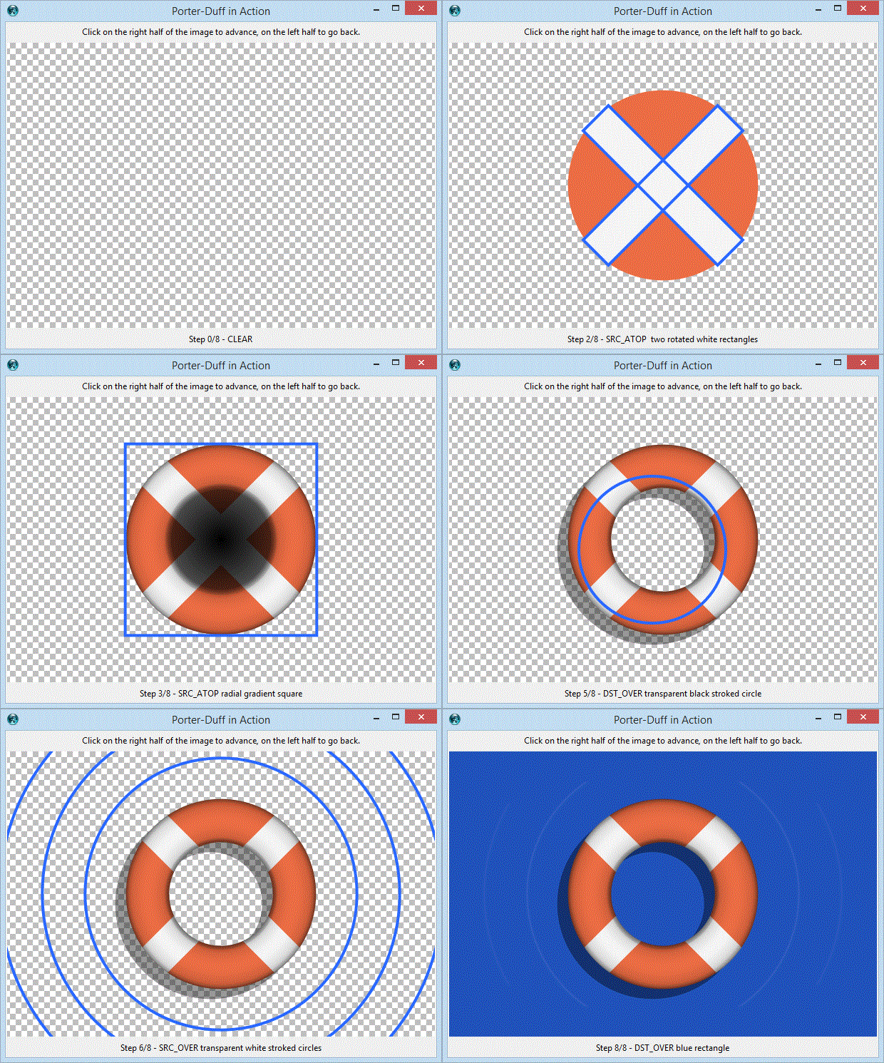
Credits to https://ciechanow.ski/alpha-compositing/
TclTk binding is still at alpha stage, performances are amazing.
Here is a demo screenshot. Rotation/zoom at full-screen resolution in real-time (no flickering)
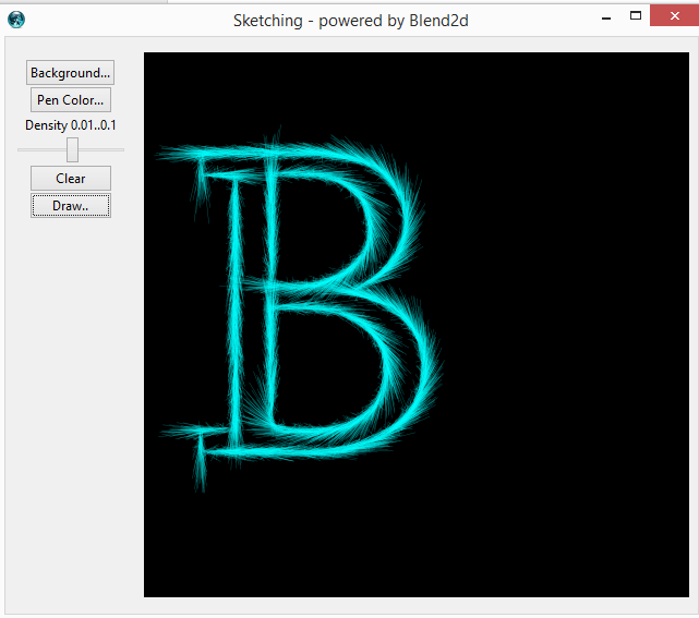
More to come..
arjen - 2020-07-17 09:43:26
Very nice - I followed the instructions and it works as described :). Haven't tried anything complicated yet, but this is encouraging.
ABU Thanks. I'm going to write a better reference manual and a sort of tutorial. Let me know what sounds complicated..
arjen - 2020-07-20 06:40:52
Wrt "complicated": I merely meant that I varied on some of the commands in the documentation and this page to see how things work. And I had a look at the demos. Especially rotating the tiger image was impressive.
EB - 2023-04-21 06:59:52
The result is pretty impressive. I had a look at the previous version and didn't find it so fast, but I will retry. I'm looking for a library for tkpath backend, the GDI+ one being a bit slow. Another alternative backend for tkpath could be skia , whose API fits very well. Another use for such library could be to create ttk element. The image element is pretty slow and such library would open a lot of possibilities.
Using Blend2d as a backend for tkpath could be a good idea. Blend2d is platform agnostic, does not require any external lib, nor GPU support, so there's no need for any diff for Windows/MacOS/Linux ...
This project of mine, TclBlend2d, had a different inspiration and goal: provide a Processing-like library for Tcl .I mean someting like processing.org, or p5js.org. I must say that I'm quite satisfied; I can code in Tcl (almost) everything I can code in Processing (except OpenGL shaders, ... but that's a totally different topic .. ) with astonishing performances.
NR - 2023-09-28 12:05:26
I find the thickness of my lines different, my first line seems much thicker than my following lines, even though the thickness is set to the same value. There is an adjustment to be done, or a misunderstanding on my side. Your demos are just amazing and beautiful and mine is not very nice...
package require Blend2d 1.0.1
set sfc [image create blend2d -format {500 400}]
$sfc configure -fill.style [BL::color white]
$sfc clear

set xmin 51.8
set ymin 362.0
set xmax 480.5
set ymax 20.0

$sfc stroke [BL::line [list $xmin $ymin] [list $xmax $ymin]] -width 1 -style [BL::color #6E7079]
$sfc stroke [BL::line [list $xmin $ymin] [list $xmin [expr {$ymin + 5}]]] -width 1 -style [BL::color #6E7079]

set distance [expr {($ymax - $ymin) / 5.0}]
set start $ymin

for {set i 0} {$i < 5} {incr i} {
    set start [expr {$start + $distance}]
    $sfc stroke [BL::line [list $xmin $start] [list $xmax $start]] -width 1 -style [BL::color #E0E6F1]
}

label .x -image $sfc -width 500 -height 400
pack .x -fill both -expand 1
#
ABU Try to look at those lines with a screen-magnifier (e.g. Meeazure for Windows). If you look at those horizontal lines having width (thickness) 1 pixel, you can see they are differently spread over two pixels. This is because a y-coord like 51.8 means that color is blended over pixels 51 and 52. If the decimal part were different (e.g, y=51.6), the true color of these pixels will be different again....
If you want horizontal lines exactly 1 pixel thick, you should put them *at the center of the pixel*, i.e. at y=51.5. Note the if you put the line at y=51.0 or at y=52.0, then the line is spread over two pixels again. Alternatively, you could set -stroke.width less than 1.0 . eg. 0.33. In this case you will observe lines spread exactly over1 pixel (less than one pixel is hard ...), but with a reduced color intensity (that's because 'theoretically' the line occupies just 1/3 of the pixel ..)
Color theory is complex, and I don't know the details about how the colors are blended, but this is how anti-aliasing is implemented in Blend2d.
NR - 2023-09-29 08:19:33
Thanks , it works. I still have a few questions.
- Is it possible to get font informations , like font metrics ... Tk commands ?
ABU Currently support for font is incomplete and limited; text metrics will be available with the next release (I think within a couple of weeks at most)
- Is it possible to save the current state of my surface at time t, so that I can reuse it whenever I want? For example, I want to draw a circle, a rectangle... and have the option of deleting my circle but not my rectangle.
ABU No. Blend2d is an API for immediate-mode graphics (see also tclcairo) . Blend2d has no concept of scene (or display list like in 'Tk-canvas or in zinc). Tk-canvas, or zinc are APIs for retained-mode graphics. If you want to delete a circle in immediate-mode graphics, you should clean all the Surface and then redraw everything but that circle. Blend2d is very similar to https://processing.org or https://p5js.org , Even without a scene, these languages can generate amazing images and animations that are impossible to generate with an API working in retained-mode.
NR - 2023-10-04 09:00:02
Okay, I thought it was possible, via these 2 blend2D functions BLContext::save() & BLContext::restore() .
ABU It depends on what you mean with 'the State of a Surface' . In your original question, you talked about saving the objects/primitives drawn on on Surface and then be able to change some parts of what you have drawn. This is perfectly doable with a retained-mode API such as Tk-canvas, but it's impossible to do with an immediate-mode API. Simply, after you paint some circles or lines.. all you have is a painted bitmap, no concept of circles, lines, and so on is 'retained'. It's up to you to repaint these (changed) graphic primitives. Regarding the cited BLContext::save restore methods, they are still present in tcl-Blend2d (renamed as push/pop), but they are just to save the current 'state of a Context', i.e the current stroke-width, the current stroke-style (color or gradient or color) as well as the fill-style, the current transformation matrix and so on. The 'state' is just a small set of drawing attributes, it's not a 'scene' or a 'display-list'.
- Do you have any tips for drawing thousands of circles? and changing the coordinates of a circle without necessarily redrawing all the circles?
On the tclBlend2d side, I suppose this won't be a problem, but on the Tcl side, looping through my list of coordinates each time is a performance issue.
ABU I hope you can take some inspiration from Blend2d Gallery, but in general, if you need to paint and update a complex, huge, mutable scene, you need a different tool, a tool like tk-canvas, able to retain, mark and manipulate a display-list. Anyway, if you can elaborate on what you want to draw, I could give you more specific tips
NR - 2023-10-04 14:12:58
Thank you for this clarification. My goal is to draw a surface, in this surface I would like to draw a rectangle which are the edges of my surface. In this rectangle, I would like to draw circles (hundreds to thousands of circles). Depending on the movement of my mouse and its coordinates, each time I find a circle, I'd like to enlarge the diameter of that circle, and vice versa, when I leave the previously enlarged circle, I'd like it to return to its initial state.
I'm trying to get some inspiration from HTML canvas and see if tclBlend2d can do the same thing (I think it can, I hope so!), but it's the Tcl side that gives me trouble...
ABU Well, with something like Tk-canvas this can be done with few lines of code (about..20 lines), but I imagine you plan to add more requirements Tk-canvas cannot support. Using Blend2d, you should store your huge list of circles and then scan the whole list every time the mouse moves. (..you can also think to implement a quad-tree subdivision of the 2D-plane, but this is stuff for C, not for Tcl) and "worse", when you hit the circle to modify, you should update your list of circles, and then redraw everything from scratch. I predict bad performances with 1000 circles. I can be wrong, but I've never seen anything like it done in Blend2d or friends ... I suggest to play with p5js.org; apart from the different language (Javascript vs Tcl), they are very similar in approach. If you like p5js approach, and you love Tcl, probably you will reconsider Blend2d (...warning ... , Blend2d just covers the core features of p5js; p5js provides a huge number of extended libraries)
NR - 2023-10-05 08:42:31
Thank you Aldo , for the advice , in the end your library does not correspond to my needs. I thought I could replace that ugly old Tk canvas... It's a pity.
RZ You could try tkpath from androwish.org or tko::path from https://chiselapp.com/user/rene/repository/tko
NR - 2023-12-27 12:21:22
My intention is to make this demo , but I find that the brightness is not perfect. Can you give me some advice? The author uses HSL here I use HSB, I don't know if that's the problem.
ABU HSB (aka HSV) and HSL are different color models (see https://en.wikipedia.org/wiki/HSL_and_HSV ).
Anyway you can use this conversion utility (it will be included in the next Blend2d release)
proc HSL {h s l {alpha 1.0}} {
        set v [expr {$l+$s*min($l,1-$l)}]
        set sat [expr {$v==0 ? 0.0 : 2*(1-$l/$v)}]
        HSB $h $sat $v $alpha
}
# Ported from Rainbow Rain animation:
# https://onaircode.com/awesome-html5-canvas-examples-source-code/
# https://codepen.io/towc/pen/VYbYvQ
package require Blend2d
proc HSL {h s l {alpha 1.0}} {
# ABU conversion utility :
set v [expr {$l+$s*min($l,1-$l)}]
set sat [expr {$v==0 ? 0.0 : 2*(1-$l/$v)}]
return [HSB $h $sat $v $alpha]
}
proc anim {} {
global sfc w h dots dotsVel accelleration repaintColor
global total occupation size portion
$sfc clear -style $repaintColor
for {set i 0} {$i < $total} {incr i} {
set currentY [expr {$dots($i) - 1}]
set dots($i) [expr {$dots($i) + $dotsVel($i) + $accelleration}]
set hsl [HSL [expr {$portion * $i}] 0.8 0.5] ; # conversion utility
$sfc fill [BL::rect [expr {$occupation * $i}] $currentY $size [expr {$dotsVel($i) + 1}]] -style $hsl
if {($dots($i) > $h) && (rand() < 0.01)} {
set dots($i) 0
set dotsVel($i) 2
}
}
update
after idle anim
}
set w 800
set h 400
set total $w
set accelleration 0.05
set size [expr {$w / $total}]
set occupation [expr {$w / double($total)}]
set repaintColor [BL::rgb 0 0 0 0.04]
set portion [expr {360 / double($total)}]
for {set i 0} {$i < $total} {incr i} {
set dots($i) $h
set dotsVel($i) 10
}
wm title . "TclTk binding for Blend2d - Rainbow Rain animation"
set sfc [image create blend2d -format [list $w $h]]
label .x -image $sfc -borderwidth 0 ; pack .x
animNR - 2023-12-27 18:14:01
Thanks, it's much better, I've modified my code to include your utility.
NR - 2023-12-28 19:29:15
Small contribution according to this demo .
set thisDir [file normalize [file dirname [info script]]]
set auto_path [linsert $auto_path 0 [file dirname $thisDir]]

# Ported from Fireworks animation:
# https://onaircode.com/awesome-html5-canvas-examples-source-code/
# https://codepen.io/programking/pen/AJgeEd?editors=1111
package require Blend2d

proc random {min max} {
    return [expr {rand() * ($max - $min) + $min}]
}

proc calculateDistance {p1x p1y p2x p2y} {
    set xDistance [expr {$p1x - $p2x}]
    set yDistance [expr {$p1y - $p2y}]

    return [expr {pow($xDistance, 2) + pow($yDistance, 2)}]
}

proc setParticle {value} {
    global PARTICLECOUNT
    set PARTICLECOUNT [expr {int($value)}]
}

proc createParticles {x y} {
    global PARTICLES PARTICLECOUNT
    for {set i 0} {$i < $PARTICLECOUNT} {incr i} {
        lappend PARTICLES [Particle new $x $y]
    }
}

proc HSL {h s l {alpha 1.0}} {
    set v [expr {$l+$s*min($l,1-$l)}]
    set sat [expr {$v==0 ? 0.0 : 2*(1-$l/$v)}]
    return [HSB $h $sat $v $alpha]
}

proc loop {} {
    global HUE SFC REPAINTCOLOR FIREWORKS PARTICLES
    global TIMERTICK TIMERTOTAL MOUSEDOWN CW CH MX MY
    global LIMITERTICK LIMITERTOTAL PARTICLECOUNT FONT

    set HUE [expr {$HUE + 0.5}]

    $SFC clear -style $REPAINTCOLOR

    $SFC fill [BL::text {0 21} $FONT "Particle count : $PARTICLECOUNT"] -fill.style [HSL $HUE 1 0.5 0.8]
    $SFC fill [BL::text {835 21} $FONT "Click on the surface..."] -fill.style [HSL $HUE 1 0.5 0.8]

    for {set i [expr {[llength $FIREWORKS] - 1}]} {$i >= 0} {incr i -1} {
        set obj [lindex $FIREWORKS $i]
        $obj draw
        $obj update $i
    }

    for {set i [expr {[llength $PARTICLES] - 1}]} {$i >= 0} {incr i -1} {
        set obj [lindex $PARTICLES $i]
        $obj draw
        $obj update $i
    }

    if {$TIMERTICK >= $TIMERTOTAL} {
        if {!$MOUSEDOWN} {
            lappend FIREWORKS [Firework new [expr {$CW / 2.}] $CH [random 0 $CW] [random 0 [expr {$CW / 2.}]]]
            set TIMERTICK 0
        }
    } else {
        incr TIMERTICK
    }

    if {$LIMITERTICK >= $LIMITERTOTAL} {
        if {$MOUSEDOWN} {
            lappend FIREWORKS [Firework new [expr {$CW / 2.}] $CH $MX $MY]
            set LIMITERTICK 0
        }
    } else {
        incr LIMITERTICK
    }

    update
    after idle loop
}

oo::class create Firework {

    variable _x
    variable _y
    variable _sx
    variable _sy
    variable _tx
    variable _ty
    variable _distanceToTarget
    variable _distanceTraveled
    variable _coordinates
    variable _coordinateCount
    variable _angle
    variable _speed
    variable _acceleration
    variable _brightness
    variable _targetRadius

    constructor {sx sy tx ty} {

        set _x $sx
        set _y $sy
        set _sx $sx
        set _sy $sy
        set _tx $tx
        set _ty $ty
        set _distanceToTarget [calculateDistance $sx $sy $tx $ty]
        set _distanceTraveled 0
        set _coordinates {}
        set _coordinateCount 3
        for {set i 0} {$i < $_coordinateCount} {incr i} {
            lappend _coordinates [list $_x $_y]
        }
        set _angle [expr {atan2($ty - $sy, $tx - $sx)}]
        set _speed 2
        set _acceleration 1.05
        set _brightness [random 50 70]
        set _targetRadius 1
    }

    method update {index} {
        global FIREWORKS

        set _coordinates [lrange $_coordinates 0 end-1]
        set _coordinates [linsert $_coordinates 0 [list $_x $_y]]

        if {$_targetRadius < 8} {
            set _targetRadius [expr {$_targetRadius + 0.3}]
        } else {
            set _targetRadius 1
        }

        set _speed [expr {$_speed * $_acceleration}]
        set vx [expr {cos($_angle) * $_speed}]
        set vy [expr {sin($_angle) * $_speed}]

        set _distanceTraveled [calculateDistance $_sx $_sy [expr {$_x + $vx}] [expr {$_y + $vy}]]

        if {$_distanceTraveled >= $_distanceToTarget} {
            createParticles $_tx $_ty
            set FIREWORKS [lreplace $FIREWORKS $index $index]
        } else {
            set _x [expr {$_x + $vx}]
            set _y [expr {$_y + $vy}]
        }

    }

    method draw {} {
        global SFC HUE FONT PARTICLECOUNT

        set hsl [HSL $HUE 1 $_brightness]

        set path [BL::Path new]
        $path moveTo [list [lindex $_coordinates end 0] [lindex $_coordinates end 1]]
        $path lineTo [list $_x $_y]
        $path close
        $path arcTo [list $_tx $_ty] [list $_targetRadius $_targetRadius] 0 [expr {3.14 * 2}]
        $SFC stroke $path -style $hsl
        $path destroy

    }
}

oo::class create Particle {

    variable _x
    variable _y
    variable _coordinates
    variable _coordinateCount
    variable _angle
    variable _speed
    variable _friction
    variable _gravity
    variable _hue
    variable _brightness
    variable _alpha
    variable _decay

    constructor {x y} {
        global HUE

        set _x $x
        set _y $y
        set _coordinates {}
        set _coordinateCount 5
        for {set i 0} {$i < $_coordinateCount} {incr i} {
            lappend _coordinates [list $_x $_y]
        }
        set _angle [random 0 [expr {3.14 * 2}]]
        set _speed [random 1 10]
        set _friction 0.95
        set _gravity 1
        set _hue [random [expr {$HUE - 20}] [expr {$HUE + 20}]]
        set _brightness [random 50 80]
        set _alpha 1
        set _decay [random 0.015 0.03]
    }

    method update {index} {
        global PARTICLES

        set _coordinates [lrange $_coordinates 0 end-1]
        set _coordinates [linsert $_coordinates 0 [list $_x $_y]]

        set _speed [expr {$_speed * $_friction}]
        set _x [expr {$_x + cos($_angle) * $_speed}]
        set _y [expr {$_y + sin($_angle) * $_speed + $_gravity}]

        set _alpha [expr {$_alpha - $_decay}]

        if {$_alpha <= $_decay} {
            set PARTICLES [lreplace $PARTICLES $index $index]
        }

    }

    method draw {} {
        global SFC HUE

        set path [BL::Path new]
        $path moveTo [list [lindex $_coordinates end 0] [lindex $_coordinates end 1]]
        $path lineTo [list $_x $_y]
        $SFC stroke $path -style [HSL $HUE 1 $_brightness $_alpha]
        $path destroy
    }
}

set CW 1000
set CH 600
set PARTICLES {}
set FIREWORKS {}
set HUE 120
set LIMITERTOTAL 5
set LIMITERTICK 0
set TIMERTOTAL 80
set TIMERTICK 0
set MOUSEDOWN false
set REPAINTCOLOR [BL::rgb 0 0 0 0.5]
set MX 0
set MY 0
set PARTICLECOUNT 30

wm title . "TclTk binding for Blend2d - Fireworks"
wm resizable . 0 0

set SFC [image create blend2d -format [list $CW $CH]]
label .x -image $SFC -borderwidth 0
ttk::scale .scale -orient h -from 30 -to 600 -variable PARTICLECOUNT -command setParticle

pack .x
pack .scale -expand 1 -fill both

set fontface [BL::FontFace new "$thisDir/Blacksword.otf"]
set FONT     [BL::Font new $fontface 20.0]

bind .x <Motion>        {set MX %x ; set MY %y}
bind .x <ButtonPress>   {set MOUSEDOWN true}
bind .x <ButtonRelease> {set MOUSEDOWN false}

loop
arjen - 2024-07-16 07:26:49
I have had a look at the documentation - quite useful :) - but I have a few questions still:
- What are the filters for exactly? Either I missed the explanation or there isn't one. The mechanics are explained.
Let's forget for a moment these filters.
Currently tclBlend2d has 2 special effects that can be applied to a BL::Surface
(or to a rectangular region of the surface):
  $sfc blur ....
  $sfc bw   ....
These methods are applied to what is already rendered on the Surface.

Now, filters ....   Filters are more powerful (.. I know, they would required a better documentation ...)
Filters are for applying some special effect to what are you going to draw.
Currently tclBlend2d has 3 types of filters: blur, bw and shadow

Within the demo directory you can find many small programs you can play:
  demo/sample127-spheres.tcl - draw some random circles with a shadow.
  demo/sample121-blur.tcl    - draw some 'waves' with a different blur factor.
.. and many others.

I suggest to take some of these demos and replace
   $sfc filter xxx ... {
           ... some graphical ops on $sfc
   }
   with "ignore"
   $sfc filter "ignore" ... {
           ... some graphical ops on $sfc
   }
in this way all the graphical ops (stroke, fill, copy ...) are rendered in the normal way.

Note that, by design, filters are not applied to a single graphics object;
they are applied to a tcl-script,
or better, to all the graphic-objects that will be drawn by that script.- Is it possible to use clipping? Within Plotchart I do this by hiding whatever is drawn under rectangles, but it is sometimes useful to have more general clipping areas. As Blend2d does not seem to have the possibility to change the drawing order, you need to carefully design the drawing if you need such clipping.
Clipping is not supported ... well, there're two "experimental" methods named "setclip" and "resetclip",
but they'are intentionally undocumented/unsupported because they work only on a rectangular region,
and I'm waiting for a better implementation from the Blend2d-core library.
About the drawing order, this is the plain "painter algorhytm".

Let me know if you have a particular problem of drawing order; there're many tricks ..
arjen - 2024-08-05 14:40:37
Quick question: is it possible to set individual pixels o shoul dyou use short line segments for that? Use case: things like Fern Fractal
ABU Quick answer: no. Blend2d (core library) does not expose methods for single pixel manipulation (and if there were, they would be extremely inefficient to be called by Tcl). I suggest to use small circles or small rectangles
e.g. $surface fill [BL::rect $x $y 1 1]
arjen - 2024-08-06 14:13:49
Clear enough - worth experimenting with :).
NR - 2026-07-27 16:48:50
I may have found two bugs (version 1.7), but I don't know how to file a ticket on SourceForge (it seems to be related only to one of your projects). Could you tell me what steps to follow?
ABU Just open a ticket on https://sourceforge.net/p/irrational-numbers/tickets/ . "Milestone" is not important; it's an attribute I set after evaluating the issue. Anyway, now there's a "tclBlend2d 1.x" milestone.