simulating latch behaviour in Bwise
by Theo Verelst

A latch is a memory, composed of a number of bits, which either feeds information through from its input pins to its corresponding output pins, or stores the last information on its output pins, no matter what the inputs do, under the control of a clock signal.
It is a digital circuit which is essential in computer circuits, and it is used in the page LED display driven by the parallel port under tcl control, where it is interesting to use the Tk canvas based bwise to make a circuit diagram which is interactive, simulates block behaviour, and can even on block and pin level communicate with the parallel port hardware.
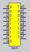
First on this page lets start making a block with 8 input and 8 output bits (0 or 1), and a clock signal input, assuming bwise has been started.
newproc {} latch {i0 i1 i2 i3 i4 i5 i6 i7 cl} {o0 o1 o2 o3 o4 o5 o6 o7}Because the pins carry signals which are either 0 or 1 in this case, we can use the space inside the block to show their value. So we make text fields, linked with the block name by common first tag (so we can keep moving the block around)
 foreach i [tag_and {latch pin typeout}] {
    set c [lrange [$mc coords [tag_and "latch $i pin"]] 2 3] ;
    $mc create text [expr [lindex $c 0] -3] [lindex $c 1] -anchor se -text X -tag "latch added value [lindex [$mc itemcget $i -tag] 3]"
 }

 foreach i [tag_and {latch pin typein}] {
    set c [lrange [$mc coords [tag_and "latch $i pin"]] 2 3] ;
    $mc create text [expr [lindex $c 0] +3] [lindex $c 1] -anchor sw -text X -tag "latch added value [lindex [$mc itemcget $i -tag] 3]"
 }
Now we can update all 'value' tagged text items from their corresponding pin variables by:
 foreach i [tag_and {latch value}] {
    $mc itemco $i -text "[set latch.[lindex [$mc itemcget $i -tag] 3]]"
 }
We can bind a procedure to the block value texts so that when we click on them, their value inverts:
 $mc bind value <Button-1> {
    global mc;
    set c [$mc find withtag current] ;
    set d [lindex [$mc itemcget $c -tag] 3];
    set e [lindex [$mc itemcget $c -tag] 0];
    if {[set $e.$d] == "1"} {set $e.$d 0} {set $e.$d 1};
    $mc itemco $c -text [set $e.$d] ;
 }
The texts are initialized with 'X' to indicate undefined, when clicked, and X becomes a 1, when clicked again, the 1 becomes 0.
After clicking, the pin-corresponding variables, easily reachable by on the yellow block using the right-mouse --> data menu, which displays all of them in a list of editable fields, are automatically updated to the inverted value.
The other way around, the update sweep from above is needed.
We still need to supply the block function for this latch block, which we could have done by specifying the first argument to the newproc procedure, but can always update manually:
 set latch.bfunc {
    if {${latch.cl} == 1} {
       for {set i 0} {$i<8} {incr i} {
          set latch.o$i [set latch.i$i]
       }
    }
 }
At this moment this test block function can be used in a bwise canvas network which is run either by Run or Funprop (see block right mouse button menu) methods, and pass its input bits to the output bits when it is Eval-ed with a '1' clock signal, and remember its values otherwise.
To make this update of the block value text feedbacks automatic without having to trace block variables or the code which accesses them, we can make an automatic update so many times per second using a function which calls itself and another function repeatedly like this:
 proc att {f {t 200}} {
    global doatt ;
    if {$doatt == 1} {
       eval $f ;
       after $t [list att $f $t]
    }
 }
The default repeat rate is 5 Hz (5x per second), unless there is too little processor time, in which case no overrun takes place, just delay, and it is necessary to set a global variable:
set doatt 1
to make the function work:
 att {
    uplevel #0 {
       foreach i [tag_and {latch value}] {
          $mc itemco $i -text "[set latch.[lindex [$mc itemcget $i -tag] 3]]"
       }
    }
 }
To stop the updates:
set doatt 0
To reset all pins, for instance after making the block in the order from this page:
foreach i [block_get_pinnames latch] {set latch.$i 0}
Before simulating the display driven by printer port circuit, lets use this setup to drive the bits of the printer port with bwise.
Assuming the above latch is present in bwise, lets make a printer output block
newproc {} lprout {i0 i1 i2 i3 i4 i5 i6 i7 cl} {}and move it to a convenient position in the bwise canvas, and connect the corresponding pins from the latch and our new block:
for {set i 0} {$i < 8} {incr i} {connect {} latch o$i lprout i$i}again we set the block function again seperately, to drive the printer port
 set lprout.bfunc {
    set o 0;
    for {set i 0} {$i < 8} {incr i} {
       set o [expr $o+[set lprout.i$i]*(1<<$i)]
    };
    lpt_wrdata $o
 }
assuming the printer port driver has been loaded
load lprtcl
See LED display driven by the parallel port under tcl control. The control latch from this circuit has been initialized to feed all three displays with the data on the printer output port.
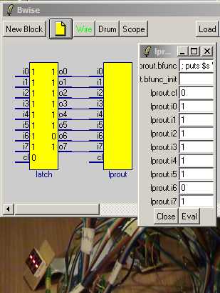
The picture above shows the resulting setup, where the bits are shown on the latch block, and the connections to the lprout block. Below, a camera capture is partly visible of the physical display circuit and the display, which actually responds live to the bits set on the latch, when the bwise menu 'funprop' is used on it to transfer data to the lprout block per bit, which sends the data to the printer port after binary to decimal converting it first.
In this setup, the displays and camera were connected to a machine in a different place than the machine running bwise with the blocks, and the printer port was driven over a socket based connection.
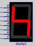
The display can also be simulated find on a bwise canvas. First, a block with the right pins and size
newproc {} display2 {i0 i1 i2 i3 i4 i5 i6 i7} {} 80 {} {} 0 0This block function sets the segments for which the corresponding input bits are one to black, otherwise to red:
 set display2.bfunc {
    for {set i 1} {$i <=8} {incr i} {
       if {[set display2.i[expr $i-1]] == 1} {
          $mc itemco [tag_and "display2 segment s$i"] -fill gray20
          } {
          $mc itemco [tag_and "display2 segment s$i"] -fill red}
    }
 }
This draws the segments on top of the block:
 set i 0;
 foreach {a b c d} {71 14 68 63  68 67 65 117  63 119 10 119  8 117 11 67  11 63 14 14  16 12 69 12  66 65 13 65  73 121 73 121 } {
    $mc create line $a $b $c $d -width 10 -fill red -tag "display2 overlay segment s[incr i]" -capstyle round
 }

 $mc itemco [tag_and {block display2}] -fill black
To design display patterns, lets make the segments click sensitive, so they invert at each click of the left mouse button:
 $mc bind segment <Button-1> {
    set i [$mc find withtag current];
    if {[$mc itemcget $i -fill] == "red"} {
       $mc itemco $i -fill gray20
    } {
       $mc itemco $i -fill red
    }
 }
and lets connect it to the latch output as well:
for {set i 0} {$i <8} {incr i} {connect {} latch o$i display2 i$i}Now both the simulated and the actual display look the same when 'funprop' is called from the latch block.
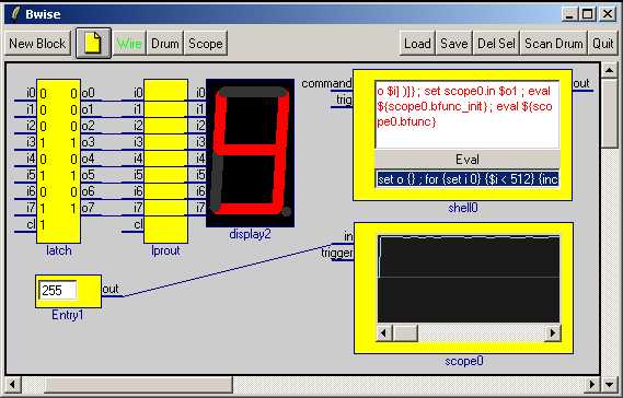
Is there use for one or more latch circuitsin computer/programming/tcl land? Yes, there is, such as simulating the circuits used the parallel port displays, but also for instane for reading data back, using the 3 state outputs of the 8 bit latch chips I used, as in the picture below, which contains the displays, a control latch, and a latch which can make data be read in via the (modern) parallel port into bwise.
The latch gets its input from a very fast AD converter chip (Burr Brown/TI ADS 831 , 60 MHz), of which the read data can be shown in a (simulated oscillo-) scope canvas block in Bwise, as a graph, while the current value is shown in an entry, which is set to automatically update and feed the block with the little woble graph.
The AD converter can also measure a nearly completely stable value when the input, fitted with a slider in this case, is free from hum (50 Hz mains field). The update is now slow, which is why I've prepared counter and memory circuits, up to the speed of the AD converter, which I'll use to store a number of sampled values, which then can be read in tcl over the limited parallel port bandwidth.
The circuit itself can be seen in
[L1 ]
As for me not aftermath (lots of interesting stuff known from electronics noise analysis to nuclear physics), lets throw a dice and see what tcl and tk can teach us about statistics in practice, and maybe some in theory...


