Bwise, a serial port tcl script and a Xilinx demo board
Bwise, a serial port tcl script and a Xilinx demo board
See Also
Description
Modern computers (except very rare quantum and analog ones) all work on the basis of binary logic, so lets see if with modern technology we can program some decent logical circuits in this case with the help of tcl and bwise.
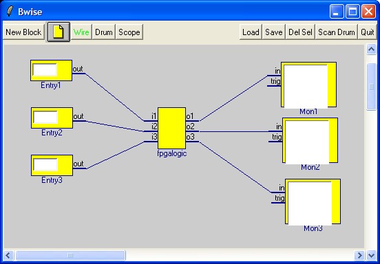
Consider this 'flow graph' or schematic:
newproc {set and.o [expr ${and.i1} & ${and.i2}]} and {i1 i2} o 40 {} {} 290 110
newentry 60 30 {} {} 72 108
newmon 0 80 65 {} {} 410 110
newproc {set bits.o2 [expr (${bits.i} & 2) >> 1] ; set bits.o1 [expr ${bits.i} & 1]} bits i {o1 o2} 40 {} {} 188 108
connect wire0 Entry1 out bits i
connect wire1 and o Mon1 in
connect wire2 and i1 bits o1
connect wire3 and i2 bits o2
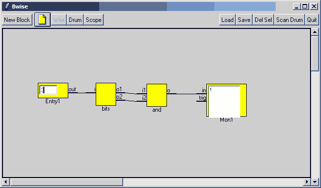
which when loaded (or sourced in the console) in bwise looks like:
The point is that we fill in a bit pattern (as number between 0 and 3, 2 bits), take the and function of the two bits in that number, and show the result as 0 or 1 (in this case).
Now we want to make a Xilinx FPGA (Field Programmable Gate Array) which can be bought cheap enough to do our and function for us in 'hardware'. Such a chip is programmed to perform a certain set of logical functions at startup by reading in a pattern from ( a megabit of) flash memory, and then acts as the programmed circuit, in this case of fair complexity (a whole microcontroller can be programmed in using less than 10% of the chips resources), but we make a simple circuit: one and gate!
To get this gate of ours to work in the xilinx programmable logic chip, I prefer to also program in a (much more complicated) serial port interface, so we can use a little tcl script to talk with our AND gate over a standard serial connection at 100 kbp/s using binary data.
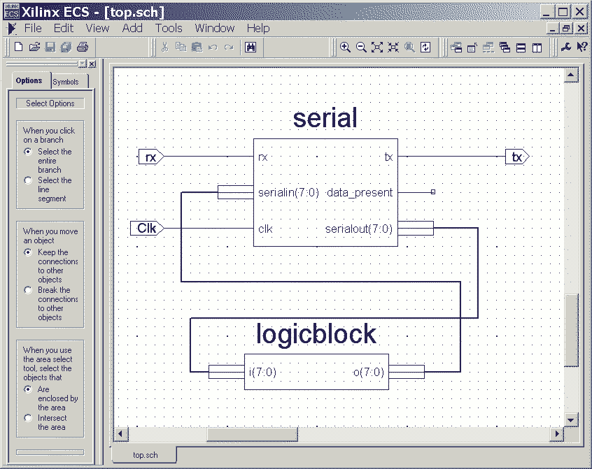
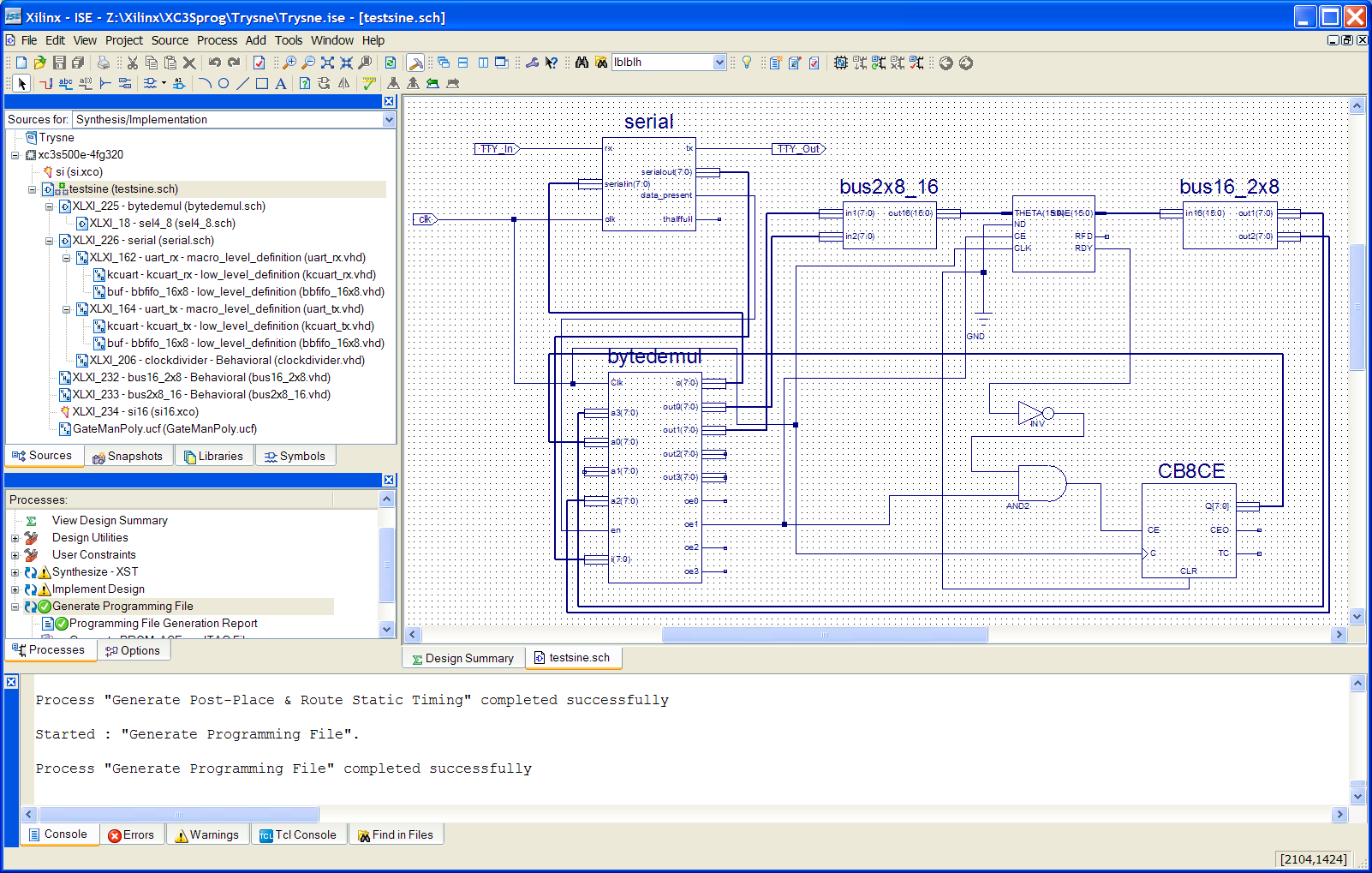
This is the schematic diagram of the setup, which at the same time is the top level of the circuit we program in the xilinx devenv's schematic entry program:
The logic block is where our and gate goes, the upper block is a compound consisting of a few levels of hierarcy of hardware description (in vhdl) which defines the serial interface, the 'out' is fed to the and gate, and the 'in' is read back 1/(50e6) sec (20 nano seconds) or so later.
So we can send a byte over the serial port, the and gives its result, which is immedeately read and send back to the serial port.
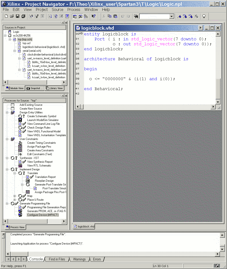
To make the xilinx act like an and function we program a block to that extend in VHDL, which can later be automated with tcl and bwise:
After this the whole circuit has been 'compiled' into a xilinx programming file using the IDE (called ISE webpack), by making a project for the right chip (in this case a xc3s200-4ft256), importing the serial source files, creating schematic symbols from the 'serial' and 'logicblock' files, and updating and saving the symbols in the serial and top schematics, and then selecting top.sch and double clicking generate programming file.
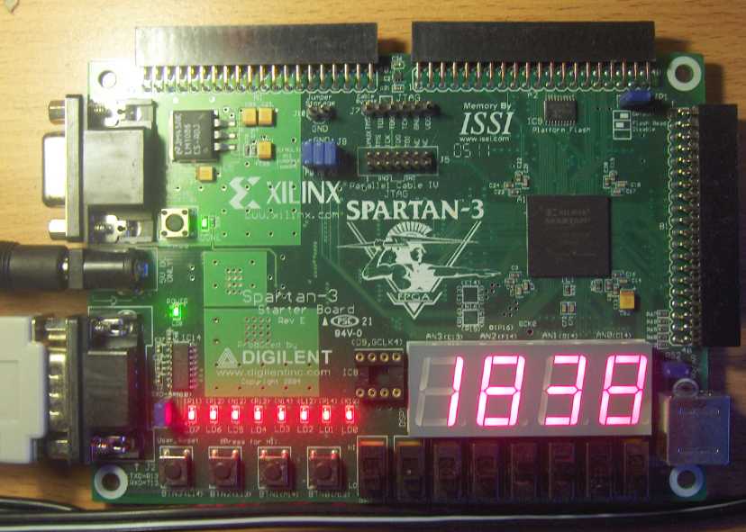
The programmer is started by double clicking 'Configure Device' , when the parallel port cable is connected with the special cable from the Digilent/Xilinx Spartan-3 starter board kit (see [L1 ] for web purchace, $99) to the jtag pins, it can search out for itself what chips are connected, in this case the fpga and a serial flash. I use direct programming in this case, so the fpga gets the top.bit file configured to it, and the flash is set to 'bypass' in the programmer. then 'program' will load the above in the xilinx chip, and the board can be connected up to the serial port.
To communicate with the result, this tcl script is used:
set fh [open COM1: RDWR]
fconfigure $fh -blocking 0 -mode 115200,n,8,1 -translation binary -buffering full
fileevent $fh readable {
    set w [read $fh] ;
    foreach c [split $w {}] {binary scan $c H* a; set v $a}
}
proc w h {
    global fh
    puts -nonewline $fh [binary format H* $h] ; flush $fh
}

fileevent stdin readable { w [gets  stdin]; }
while 1 {
    vwait v
    flush $fh
    puts -nonewline $v
    flush stdout
}
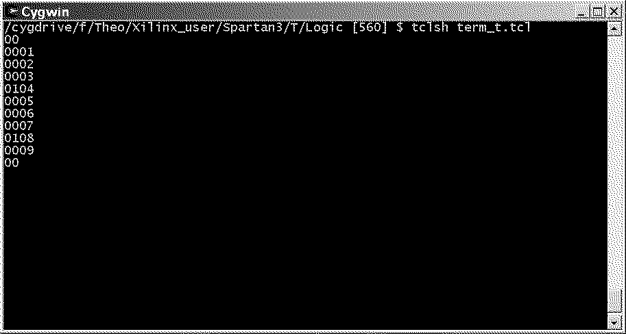
It waits for one byte in hex to be given over the keyboard (followed by <Return>) which it sends to to serial port, and then waits for a byte to get back, which is then printed on the next line in hex, while the program waits for the next input.
Input-ing all possibilities from 00 to 11 gives:
Which is correct because the output is only 1 (high) for the input combination 11(bin) which is 3(hex).
We can also change the VHDL code above to make an or gate instead of a nand:
o <= "0000000" & (i(1) or i(0));
then the result (after 'recompiling' the circuit and loading it in the chip) becomes:
00
0001
0102
0103
0100
00
which is correct too: the or is only 0 for 00 at its inputs.
TV 2005-11-20: I've installed Fedora core 4 Linux in 64 bit version on a athlon64 (3300) upgraded PC, and wondered what to do about (currently) the lack of windows (the old XP gives a blue screen in seconds...) to drive the parallel port programmer cable, and found out there is a good tool to replace IMPACT to do the actual programming of the xilinx or the flash memory, which is called xc3sprog [L2 ] which when compiled (also on 64 bit OS) nicely works by using:
./xc3sprog top.bit
And on Linux the serial script (run from a terminal, in my case a remote X terminal) probably should become (in my case):
set fh [open /dev/ttyS0 RDWR]
fconfigure $fh -blocking 0 -mode 115200,n,8,1 -translation binary -buffering full
fileevent $fh readable {
    set w [read $fh] ;
    foreach c [split $w {}] {binary scan $c H* a; set v $a}
}
proc w h {
    global fh
    puts -nonewline $fh [binary format H* $h] ; flush $fh
}

fileevent stdin readable { w [gets  stdin]; }
while {1} {
    vwait v
    flush $fh
    puts -nonewline $v
    flush stdout
}
or whatever your linux serial port is called...
This was hacked quick, so maybe some of you can say how the above script would work with redirection of the stdin from a file (in the shell that is).
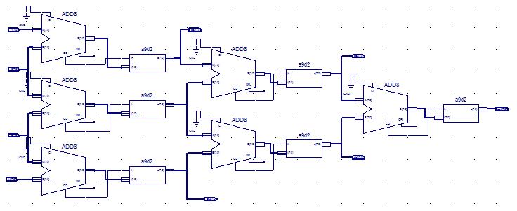
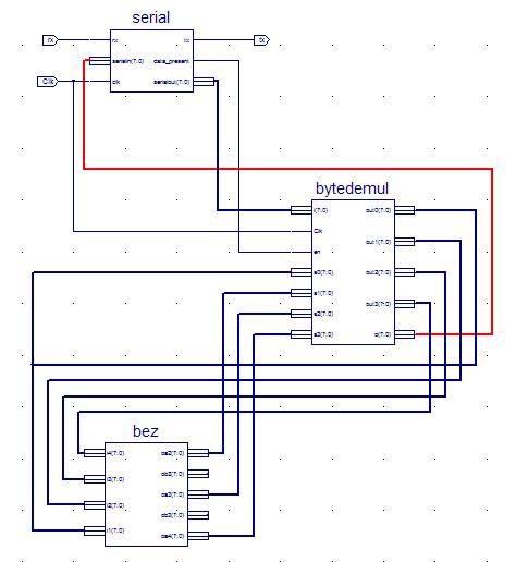
See also Bwise deCasteljau algorithm example for a hardware implementation of a bwise schematic (not automatic...) centered around a this subdivision algorithm:
It has a handy, generally usable serial interface and 4 byte demx/mux (every bytes get send to and read from a separate interface), which here drives this algorithms implementation:
The whole project for ISE can be downloaded here: [L3 ]
The tcl script can be used to input data and get (hex) data back, which cycles very four bytes, and shows the output of the subdivision, which works correct (after short test).
(more to follow on bwise simulation link and circuit generation)
I'm working on driving another much bigger FPGA project which is a sound synthesizer which is programmed over a serial link, see here: http://www.theover.org/Fpgasynth , this is NOT a design by yt, but it shoud be interesting to make a Tk interface for it.
I made a test slider, which of course is easy in Tk:
scale .sl -from 16384 -to 0 -tickinterval 1000
pack .sl -expand y -fill y
I made a serial link with the board on COM5 using 9600 kbps, and I made a test to send it a simple note on / note off message:
# open the serial port acting as MIDI
set fh [open COM5: RDWR]
fconfigure $fh -blocking 0 -mode 9600,n,8,1 -translation binary -buffering full

#A procedure to send HEX codes to the board:
proc w h {
    global fh ;
    foreach c [split $h] {
        puts -nonewline $fh [binary format H* $c]
    } ;
    flush $fh
}

# Testing with a middle C note on and noteoff (this project appears to use velocity==0 instead of noteoff message)

w { 90 3C 40 }

after 1000 {w { 90 3C 00 }}

# A system exclusive message to change the tuning of the 4 oscillators (as test)
w { F0 7F 02 00  00 00  00  F0 }
w { F0 7F 02 00  00 01  0C  F0 }
w { F0 7F 02 00  00 02  0C  F0 }
w { F0 7F 02 00  00 03  00  F0 }
w { 90 3C 10 } ; after 1600 { w { 90 3C 00 } }
It appeats to work: the 1.6 seconds tone sounds higher when the values are added 12 to.
I made a procedure to create a named window for a parameter (with major minor numbering) change slider (for starters), which at every slider change sends a parameter change message, and a test note, which is stopped when the slider is moved again, or after a few seconds.
# write a hex code to the serial port
proc w h {
    global fh
    foreach c [split $h] {
        puts -nonewline $fh [binary format H* $c]
    }
    flush $fh
}

# write system exclusive decimal encoded byte with submessage codes n1,n2
# and send a test note on, which stops after 1.6 Sec, or with a new slider move
proc wse {n1 n2 h} {
   global fh np
   foreach c [split [list F0 7F 02 00 $n1 $n2 [format "%02x" $h] F0]] {
     puts -nonewline $fh [binary format H* $c]
        }
        flush $fh
        if {$np != 0} { after cancel $np ; w { 90 3C 00 } ; set np 0 }
        w { 90 3C 20 } ; set np [after 1600 {  w { 90 3C 00 } ; set np 0}]
}

# create a new window with a slider which sends a certain message
proc newparwin {name n1 n2 max} {
    toplevel .$name
    scale .$name.sl -from $max -to 0 -tickinterval [expr $max / 20]
    pack .$name.sl -expand y -fill y
    .$name.sl conf -command  "wse $n1 $n2 "
}

# Initialize the noteplay after id variable
set np 0
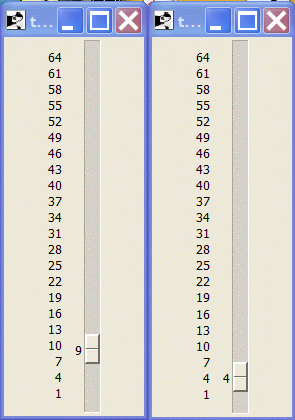
Two sliders to change the 1st and second oscillator global tuning made by these commands:
newparwin tune0 00 00 64
newparwin tune1 00 01 64
This works in practice, every slider move sends a tone to hear the difference, and the parameter changes seem to work.
TV 2008-07-04: I´ve just made this working but limited version, the next will include the two byte parameters:
# on Unix, this requires an extra procedurefile, the com port is called different, too
console show

# open the serial port acting as MIDI
#
set fh [open COM5: RDWR]
fconfigure $fh -blocking 0 -mode 9600,n,8,1 -translation binary -buffering full

# write a hex code to the serial port
#
proc w h {
    global fh
    foreach c [split $h] {
        puts -nonewline $fh [binary format H* $c]
    }
    flush $fh
}

# write system exclusive decimal encoded byte with submessage codes n1,n2
# and send a test note on, which stops after 1.6 Sec, or with a new slider move
#
proc wse {n1 n2 h} {
    global fh np
    foreach c [split [list F0 7F 02 00 $n1 $n2 [format "%02x" $h] F0]] {
        puts -nonewline $fh [binary format H* $c]
    }
    flush $fh
if {$np != 0} { after cancel $np ; w { 90 3C 00 } ; set np 0 }
w { 90 3C 20 } ; set np [after 1600 {  w { 90 3C 00 } ; set np 0}]
}

# create a new frame with a slider which sends a certain message
#
proc newparfr {name n1 n2 max} {
    frame .f1.$name
    pack .f1.$name -side left -fill y -expand y
    scale .f1.$name.sl -from $max -to 0 -length 256 -var $name
    pack .f1.$name.sl -side top -expand y -fill both -anchor center
    .f1.$name.sl conf -command  "wse $n1 $n2 "

    label .f1.$name.l -text $name -justify center
    pack .f1.$name.l -side bottom -expand n -fill x -anchor center

    entry .f1.$name.e -text $name -justify center -textvar $name -justify r -width 5
    pack .f1.$name.e -side bottom -expand n -fill x -anchor center
}

# Initialize the noteplay after id variable
set np 0

# the first frame, so that we can make some major screen groups
frame .f1
pack .f1 -side left -expand y -fill both

# commands to create various sliders
newparfr wavef1 00 2C 3
newparfr wavef2 00 2D 3
newparfr wavef3 00 2E 3
newparfr wavef4 00 2F 3
newparfr tune1 00 00 64
newparfr tune2 00 01 64
newparfr tune3 00 02 64
newparfr tune4 00 03 64

newparfr trans 01 10 64
newparfr vol 01 60 16
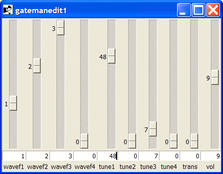
This is a screendump:
This version has all the needed sliders for the design, but the filter Q works upside down, and may not allow going to zero, but does work, too.
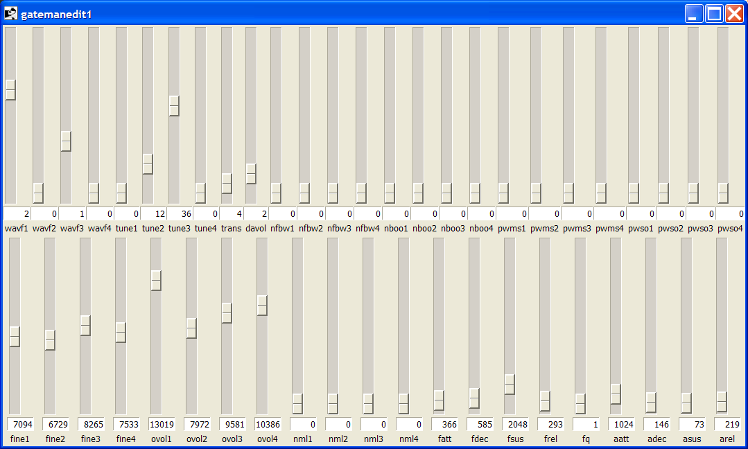
See the source file for ways to walk over the sliders in a loop to get or set all the values, or to send all of them in a batch to the synthesizer (all done in Tcl/Tk code).
Using the same setup as above, I made a sine computation work from the board, see this tcl script:
####################################################################################
#                                     FM setup                                     #
####################################################################################
##
## By Ir. Theo Verelst, http://www.theover.org
##
##
####################################################################################

# this shows the console window to see output and type Tcl/Tk commands at startup,
# close it in the console with : console hide, or comment it out here by putting
# a hash in front of it.
console show

# on Unix, this requires an extra procedurefile, the com port is called different, too
# See https://wiki.tcl-lang.org/786  and https://wiki.tcl-lang.org/447 , on Redhat e.g. : /dev/ttyS0
# the unchanged FPGA program IO rate is: 115200

# open the serial port acting as MIDI
# (fill in MOC5 and 9600 as you need)
set fh [open COM5: RDWR]
fconfigure $fh -blocking 0 -mode 9600,n,8,1 -translation binary -buffering full

# write a hex code to the serial port
#
proc w h {
    global fh
    foreach c [split $h] {
        puts -nonewline $fh [binary format H* $c]
    }
    flush $fh
}

# get a hex code to the serial port when present
#
fileevent $fh readable {
global sync
    set w [read $fh] ;
    foreach c [split $w {}] {
        binary scan $c H* a; set v $a
        puts -nonewline " $v"
        #set t3 [expr "0x$v"]
        #if {$t3 > 127} {incr t3 -256}
        #set t1 [expr 256-2*$t3]
        #set t2 [expr 256-2*$t3 +2]
        #set x [expr $sync /2]
        #switch [expr $sync %4] 0 {set col blue} 1 {set col red} 2 {set col yellow} 3 {set col green}
        if { [expr $sync %4] == 0} { puts "" }
        #.c create oval $x $t1 [expr $x+1] $t2 -fill $col -outline $col -tag gr
        # incr x
        incr sync
        # flush stdout
    }
}

update
set playnote 1

canvas .c -bg grey90 ; pack .c -expand y -fill both

puts {Sending graph data.}

.c del gr ; set x 2 ; set sync 0
for {set h 0} {$h<256} {incr h} {w FF[format "%02x" $h]0000}

puts Done.
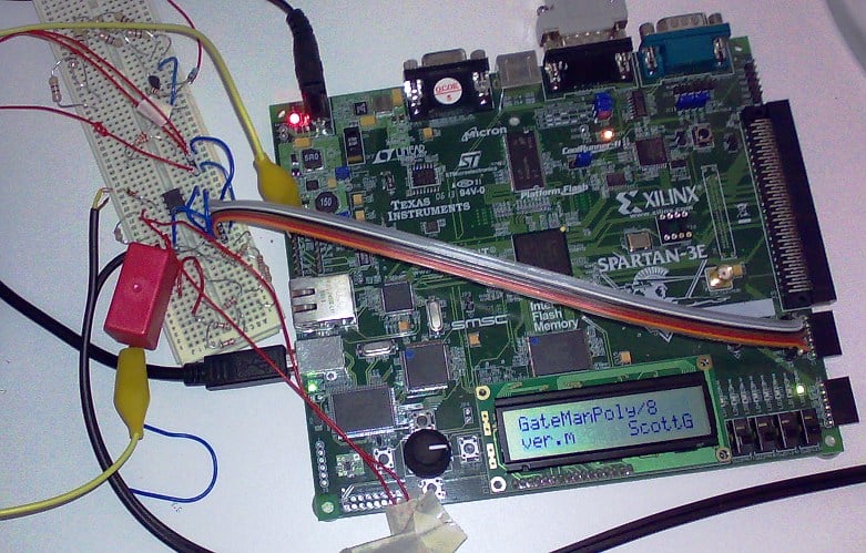
TV 2008-09-10: To make the idea of the correspondence of bwise with a hardware design more direct, I've added a small ethernet board to the setup which can be accessed from a windows machine to read and write to a fpga (and reprogram it, which is good for large spaces or notebook without serial/parallel port use), so the setup like above with the supplied communication software and example fpga program can communicate bytes to and from registers in the fpga which correspond to bwise blocks driving the hardware in realtime.
Of course the hardware blocks could also be connected through bwise, but I've not yet done that more than above, and additional functions are possible, including hardware memory structures (I will try a fast compare or indirection lookup next) also being done in tcl or for instance a fast (parallel hardware) fire-function like in BWise for fast real time block scheduling.
